SMJ Wheels and Rods
Introduction
In May 2013 I noticed a clunk presumably in the coupling rods. The loco ran on the June long weekend and the clunk was still there. Previously I had noticed that two of the cranks on the axles were slightly loose. Checking the loco showed that cranks 2, 3, and 5 were loose and also that wheel 6 was loose. This is seriously bad so it was time for some major repairs.
The cranks are secured by 1/8" roll pins that are transverse to the axle. Roll pins are great because they don't work loose. But they're not that strong and the torque from the force on the coupling rods distorted the pins and allowed movement. Also, the cranks are not a tight fit on the axle and this allowed a slight wobble.
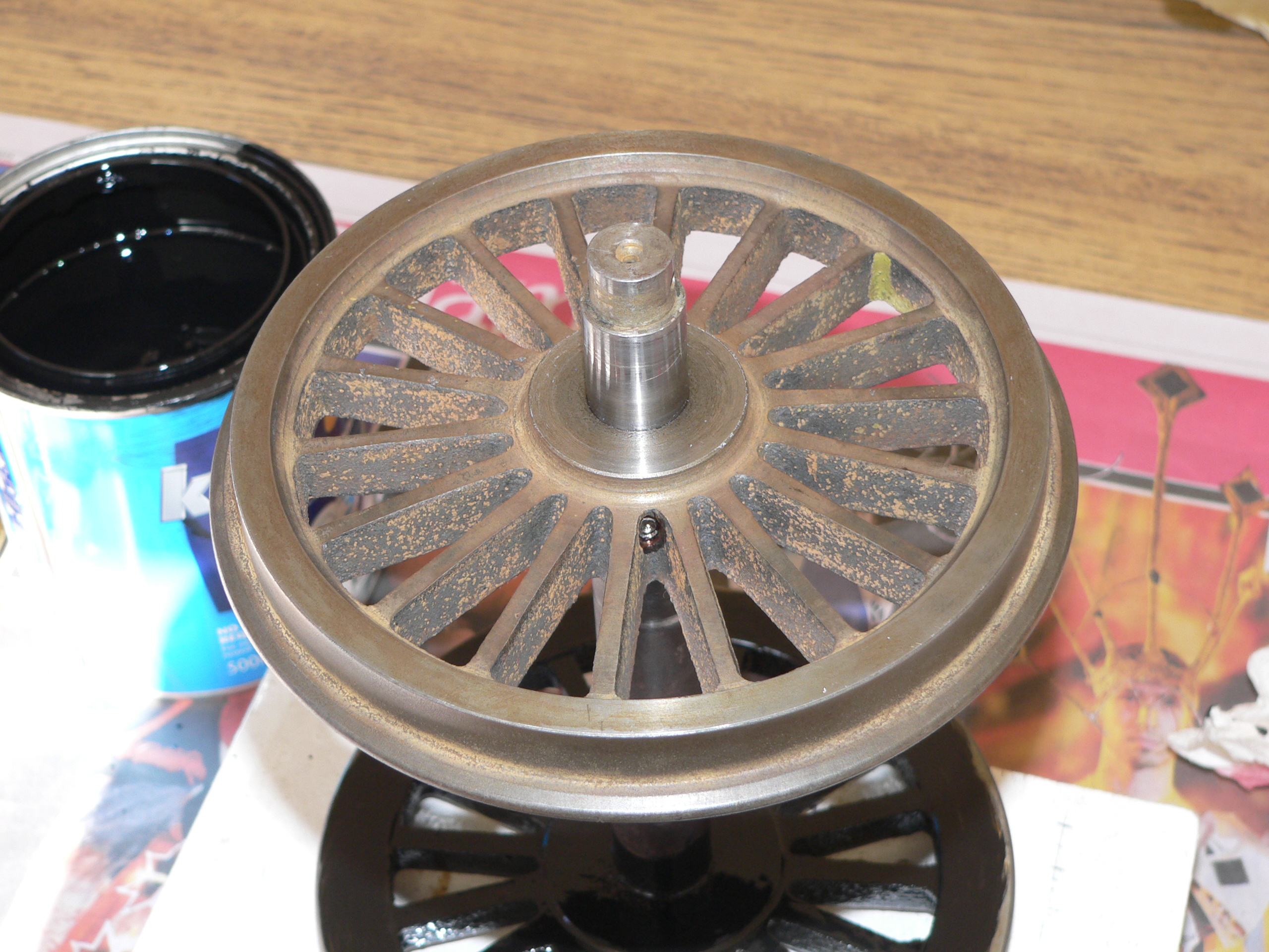
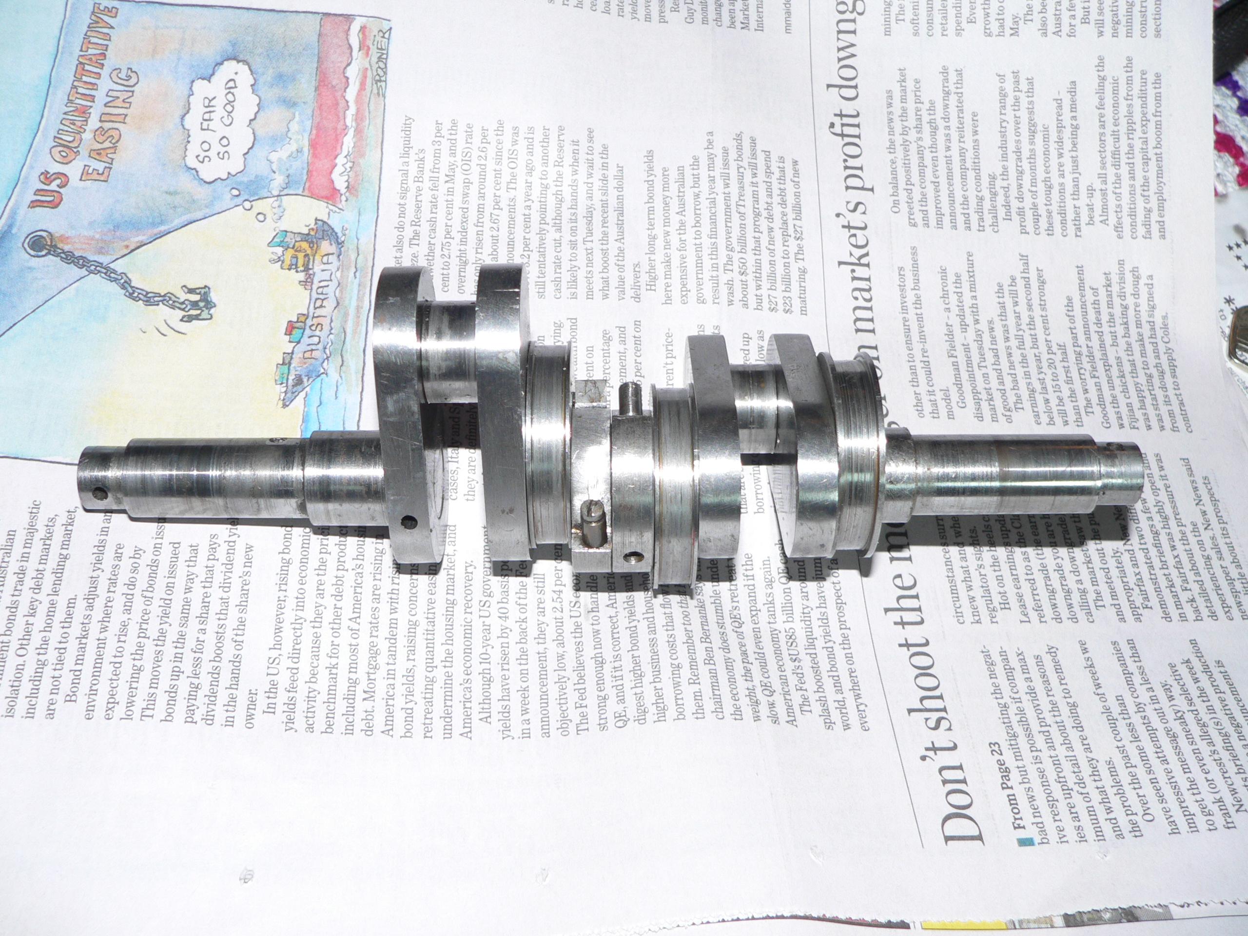
Wheel 6 was loose on the axle and yet couldn't spin on the axle. There was a roll pin that went through the hub and into a blind hole in the axle. For extra strength a pin had been pushed inside the roll pin. Considering the slop here it looks like the wheel was never a tight fit on the axle and probably secured by Loctite or glue. Using a roll pin in a blind hole is a bad idea because it's so difficult to remove it. The picture here shows the wheel with its locating pin after I'd cleaned the assembly and used Loctite 263 to secure the wheel. Notice how the pins are pushed deep inside the hole and not convenient for removal. I tried drilling the pin but it is tough steel and a drill won't touch it. Time for a tiny carbide burr unless I find a better option.
The repair effort here was later undone when extra problems were found. It took a lot of heat and force to crack the Loctite which bodes well for repairs relying on Loctite. The non-removable pin was eventually overcome by twisting the wheel backwards and forwards until the pin broke.
Removing the cranks (actually one from each axle) meant that I'd lost the quartering. I had some replacement roll pins didn't want to use them because the transverse holes for these pins don't position the cranks hard against the shoulder on the axle and because some pins aren't a tight fit they can wobble slightly. I decided to position the two cranks on the back axle and hold them against the axle shoulder and use Loctite to secure them. I planned to then enlarge the holes with a taper reamer and fit taper pins for a permanent fix.
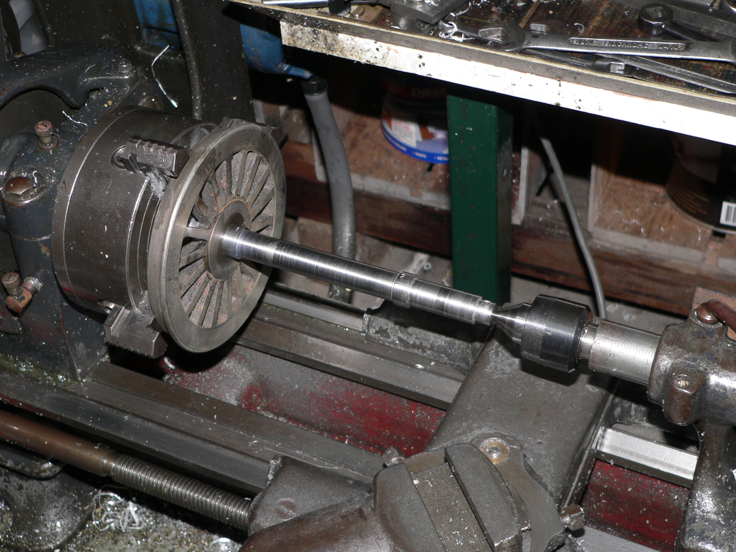
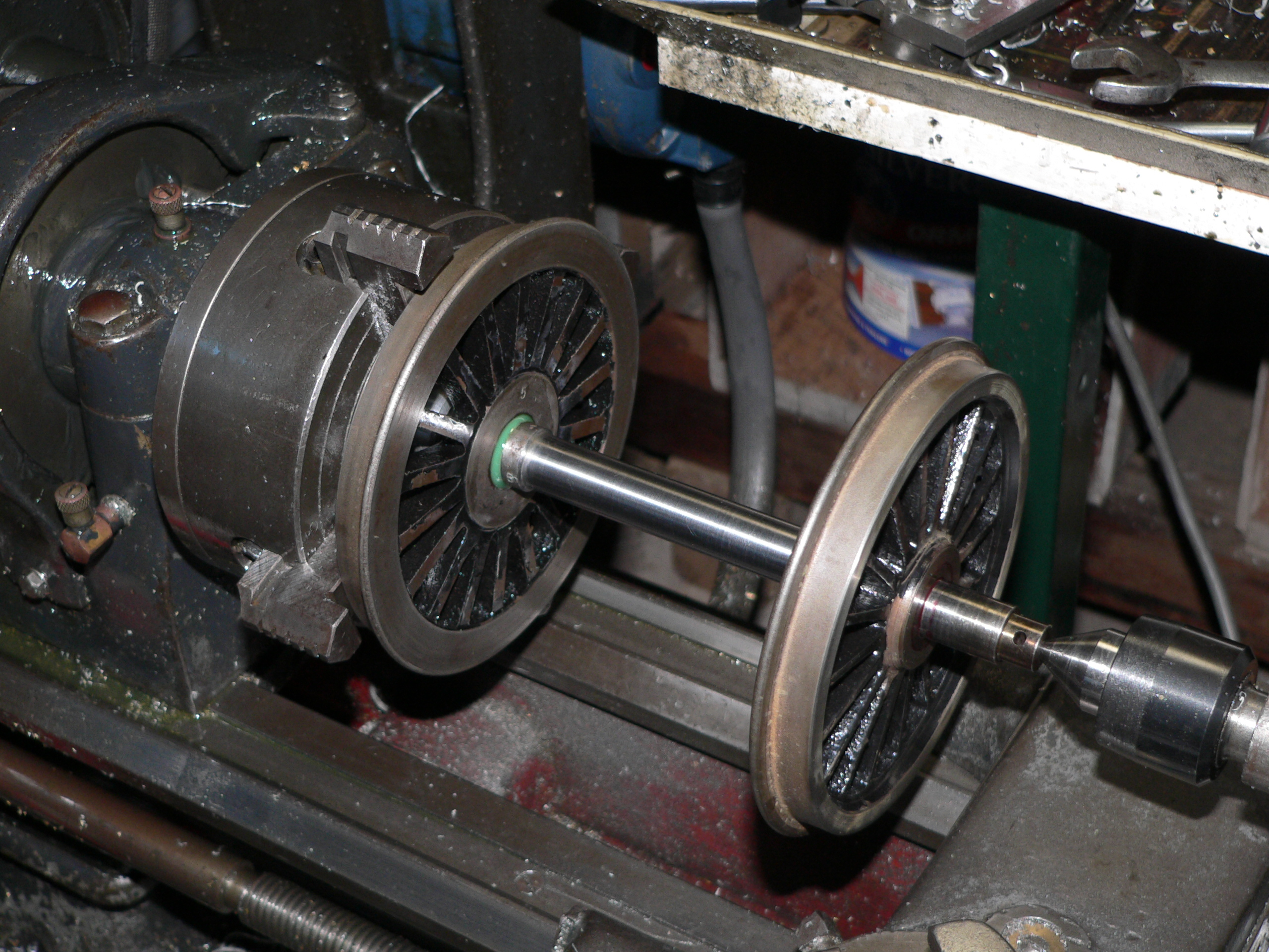
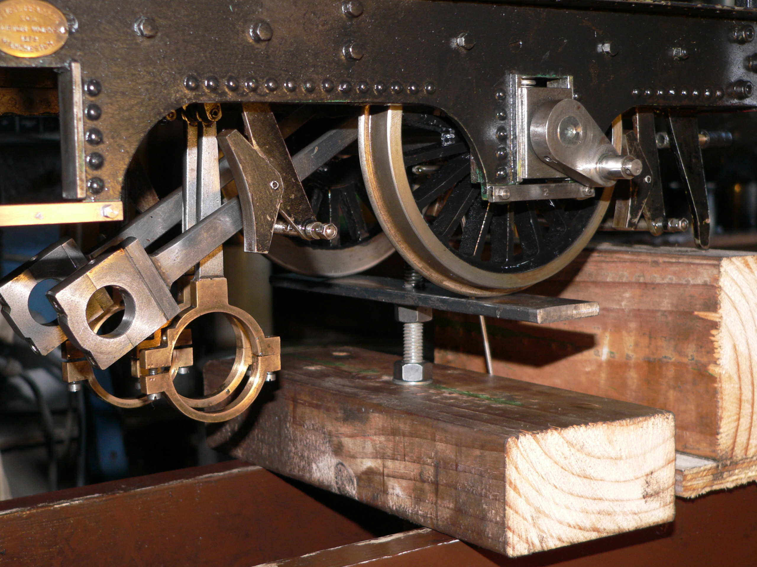
To ensure the quartering on the other axles matches this back axle I made some adjustable coupling rods. Both other axles had one crank removed. To set the length of the coupling rod I have both cranks at the forwardmost position. Once both rods have been set I have the cranks at 45° because this is the worst position for binding. The picture shows the rods in use while the Loctite on one of the driving axle cranks is curing. This approach ensures the quartering on the driving axle matches the back axle. Later I'll have the rods between the front two axles while securing the crank on the front axle. The front portion of the coupling rod has an elongated hole that allows +/- 10mm adjustment. The back portion has two holes because the axle spacing differs by 30mm.
Major setback
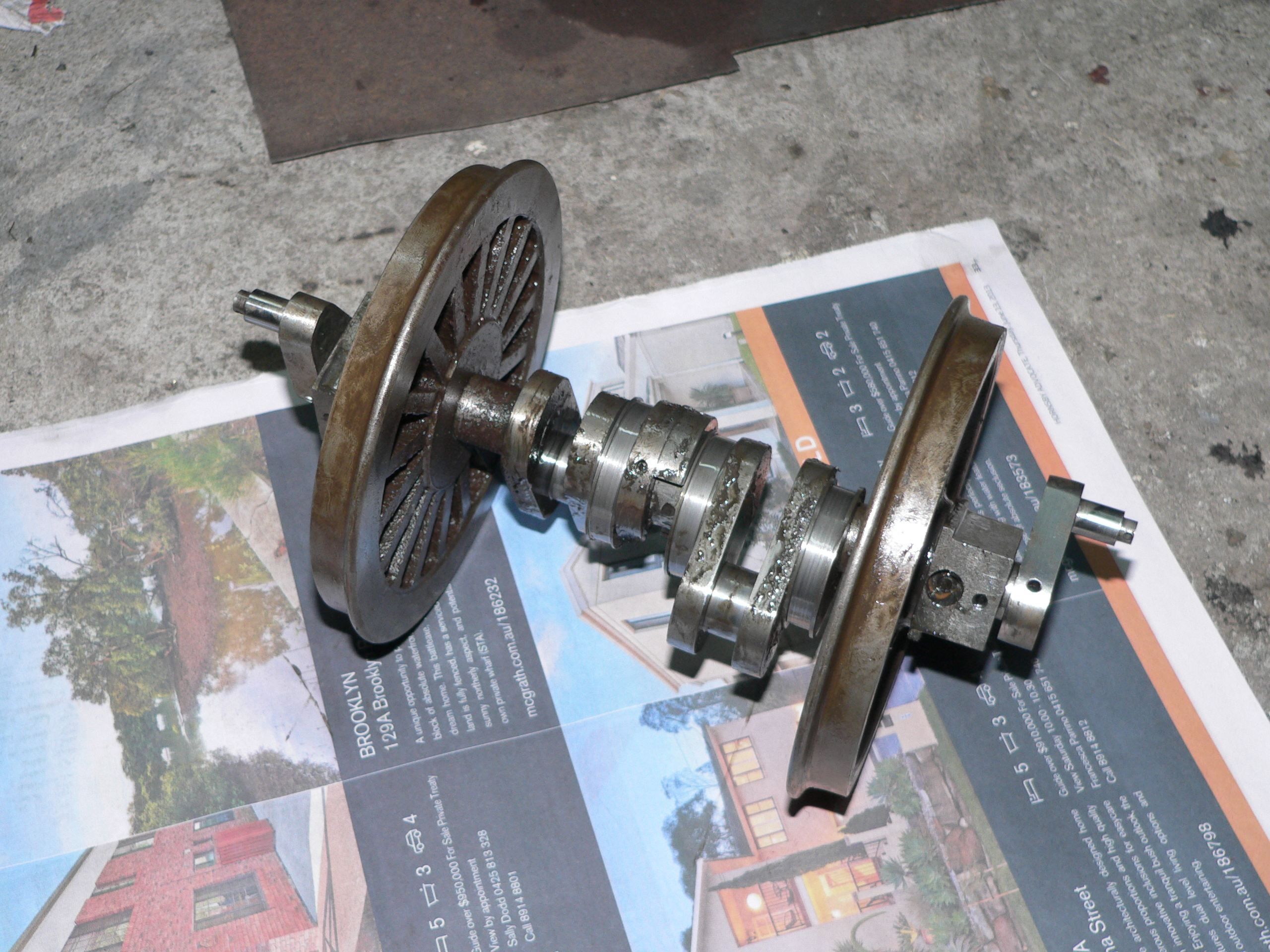
After quartering the front two axles I put the real coupling rods on and spun the wheels. Everything was smooth with no slop and no binding. Things were looking good and on the road to recovery. I decided to drop the front two axles so I could ream the locating holes and fit taper pins. After splitting the big-ends and eccentric sleeves I removed the driving axle and found that one of the wheels had a wobble. This was because the right stub-axle in this crank axle was loose in the web. Yuk, how to repair or rebuild a crank axle for inside cylinders. Both of the wheels on this axle were secured by roll pins into blind holes.
Dropping the front axle revealed that wheel 1 could spin on the axle. Neither of the wheels on this axle had roll pins so they were removable without too much trouble.
There is a bit of a design fault with the wheels because the seat on the axle is the same diameter as the journal for the axlebox. So, pressing the wheels on isn't really an option because the pressing would probably scratch the journal. Presumably the original idea was to slide the wheels on and secure them with Loctite or similar. The fitting of roll pins to some wheels was probably a later fix when the wheels broke free. An expensive solution here would be to increase the wheel bore from 5/8" to 16mm and then nickel plate the seat portion of the axle to suit. Caswell Plating has a kit for nickel plating and this costs about $200. Add $110 for a 16mm reamer. Should work but is an expensive and time-comsuming gamble.
Repair options
For crank axle repairs brazing the stub axle to the crank web sounds good except for the risk of distortion and also wrecking other fits that might be using Loctite. A safer option is to use Loctite retaining fluid. The loose joint had a parallel pin and replacing this with a taper pin should support the joint.
To secure the wheels to the axles Loctite sounds like a good first option. If this breaks and pins are required I'll try M4 grub screws through the hub and into the axle. Longitudinal pins would be better but very hard to fit as there is no step in the axle from the journal to the wheel seat.
Using taper pins to secure the cranks to the axles sounds good but I'm now thinking of using grub screws through the existing transverse holes. The holes are 3.3mm dia which is a good tapping size for M4 x 0.7. Keying the cranks using longitudinal pins will be better and this means the grub screws will just stop the cranks from coming off but not have to resist the torque from the coupling rods.
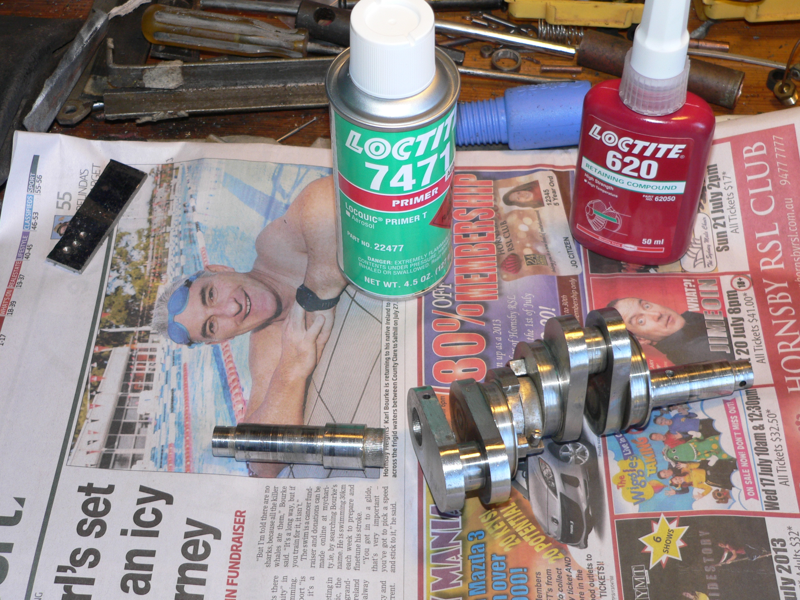
The Loctite documentation shows both 620 and 680 as high-strength retaining compounds. 680 is slightly stronger than 620 but its strength diminishes above 50°C. 620 maintains its strength at 150°C and heat aging is far less. Activators 7649 and 7471 both help 620 achieve a stronger bond. 7471 does not increase the cure rate like 7649. For safety here I want a strong bond with time to assemble the parts so I've chosen 7471 and 620.
Alignment jig
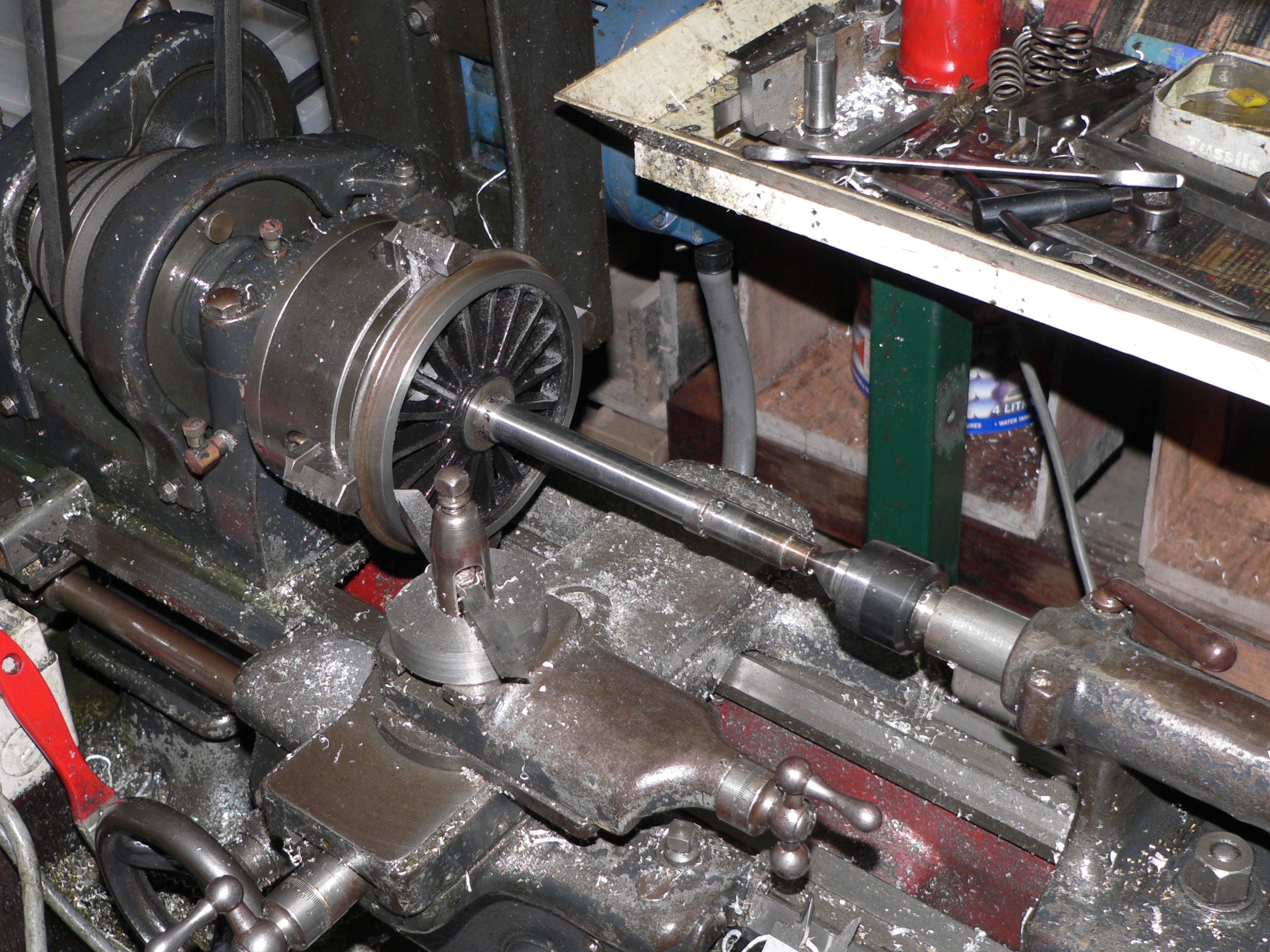
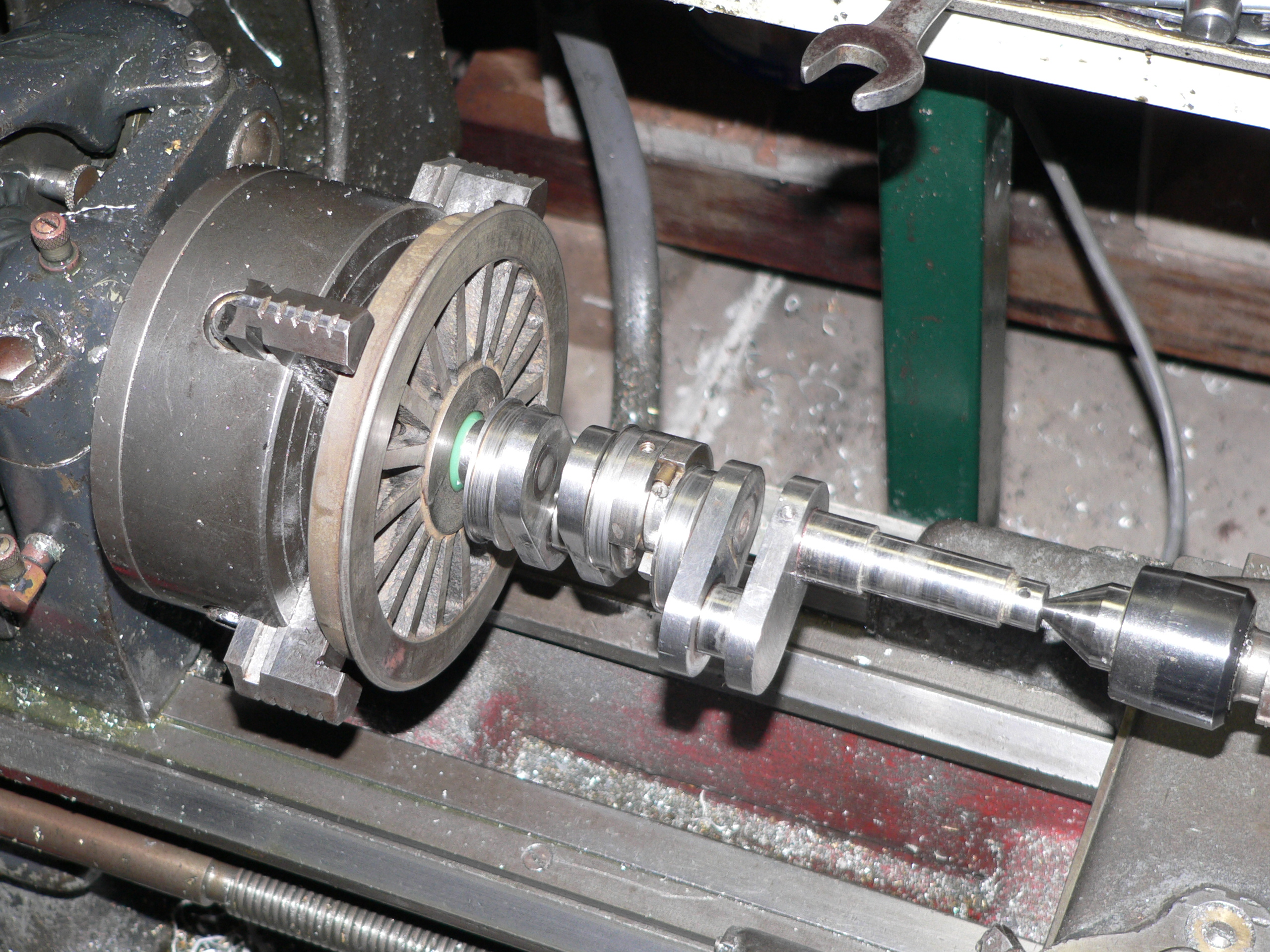
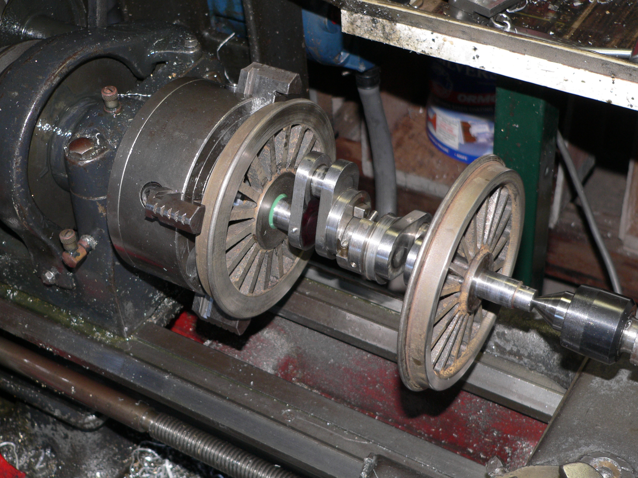
Because the wheels aren't a tight fit on the axles it isn't possible just to push them on and wait for the Loctite to set. They will probably be slightly out of true and the flanges would require machining to remove the wobble. The solution here is to make a plug that fits in the bore of my 4-jaw chuck and ream a hole in this plug to match the axle journal diameter. The height of the chuck jaws is consistent (+/- < 0.001") so pushing the wheel against these jaws will ensure it is square. This assumes that the thickness of each wheel is consistent which unfortunately wasn't the case.
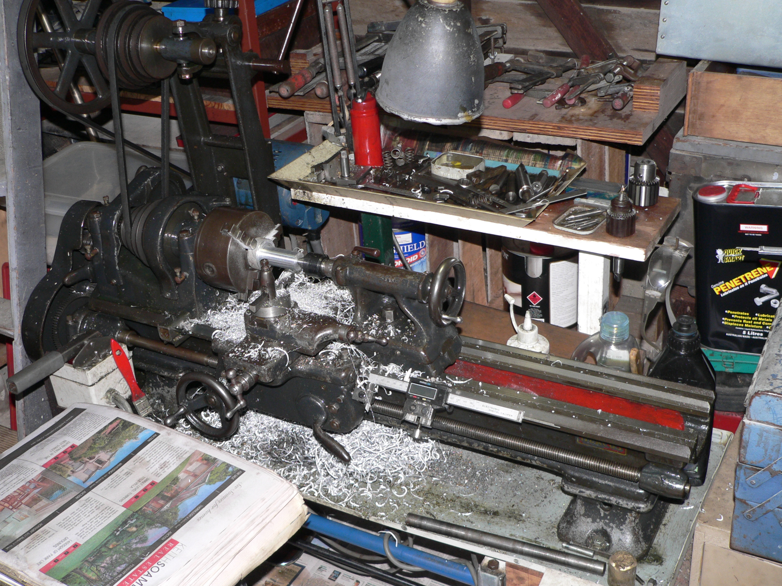
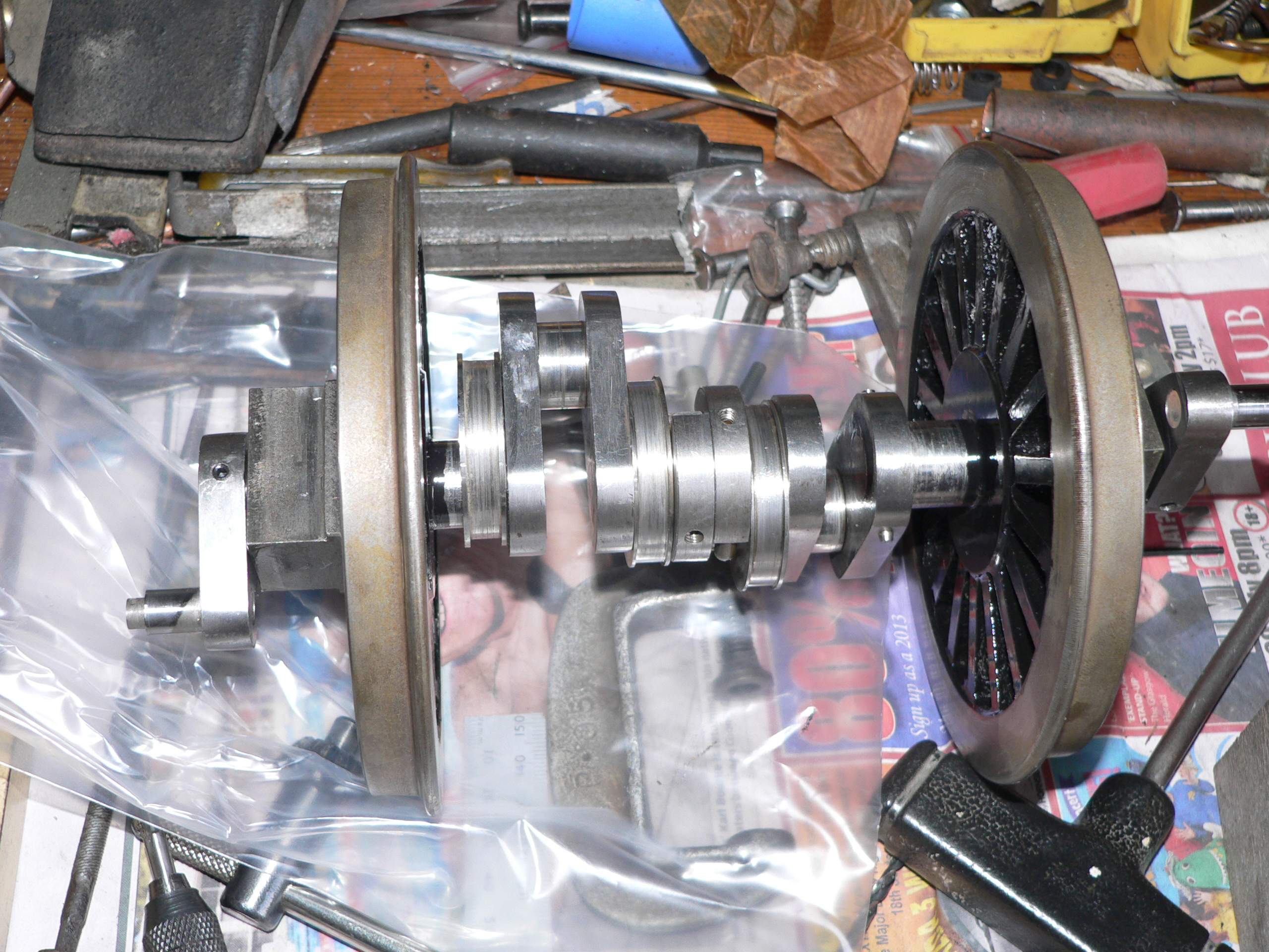
The first photo shows me turning a blob of aluminium into swarf and the plug for the chuck. Then I pushed this plug into the chuck and drilled and reamed the hole. The first job for this plug was to hold the stub axle in alignment while it was being secured to the rest of the crank axle.
For each wheel the first step was to mount it in the chuck with the front outward and trim the outer face to remove the low spots. Most wheels had about a 0.004" difference in thickness around the rim. Once this was fixed the next step was to reverse the wheel, apply Loctite, and push the axle in and apply pressure using the tailstock.

Aligning the wheels didn't work quite as well as planned. I later found that the tailstock was a bit low. The worst wheel has a 0.004" run-out. Not great but hopefully okay.
Driving axle
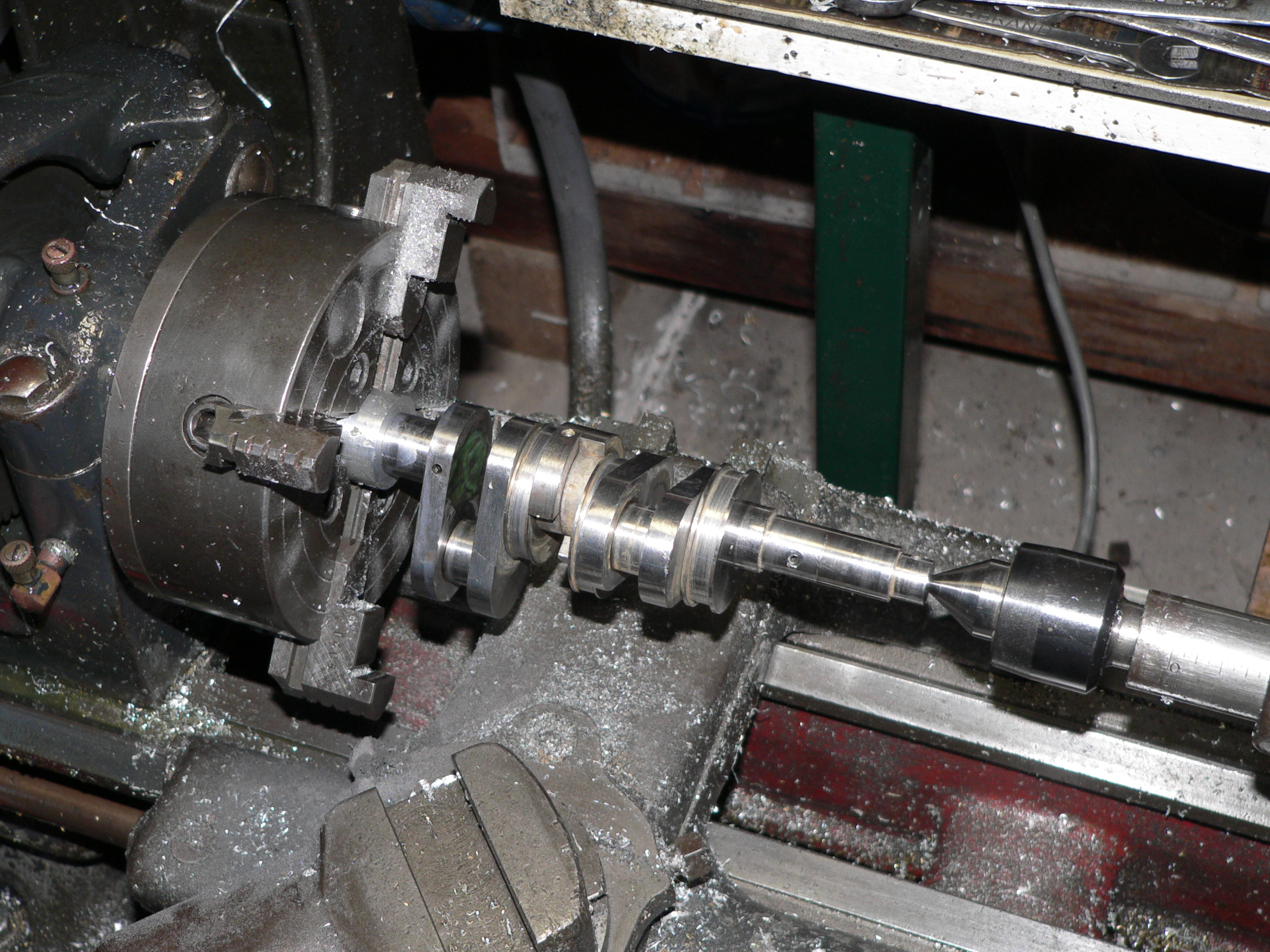
The wobbly stub axle has fine splines where it pushes into the crank web and is secured by a transverse parallel pin. Making a replacement with the splines would be very difficult. The first repair procedure here is a thorough cleaning followed by Loctite 7471 activator and then Loctite 620 retaining compound. The alignment jig (see above) is used to hold the parts in alignment while the Loctite cures.
The 1/8" dia pin that secured the stub axle was slightly bent and worn. Rather than reaming the hole and fitting a taper pin I decided to make a new pin from 1/8" silver steel and secure it with Loctite 263. The next step was to refit the wheels and secure them with 7471 and 620. Once cured I coated the outside of the joint with 263 and let it soak in.
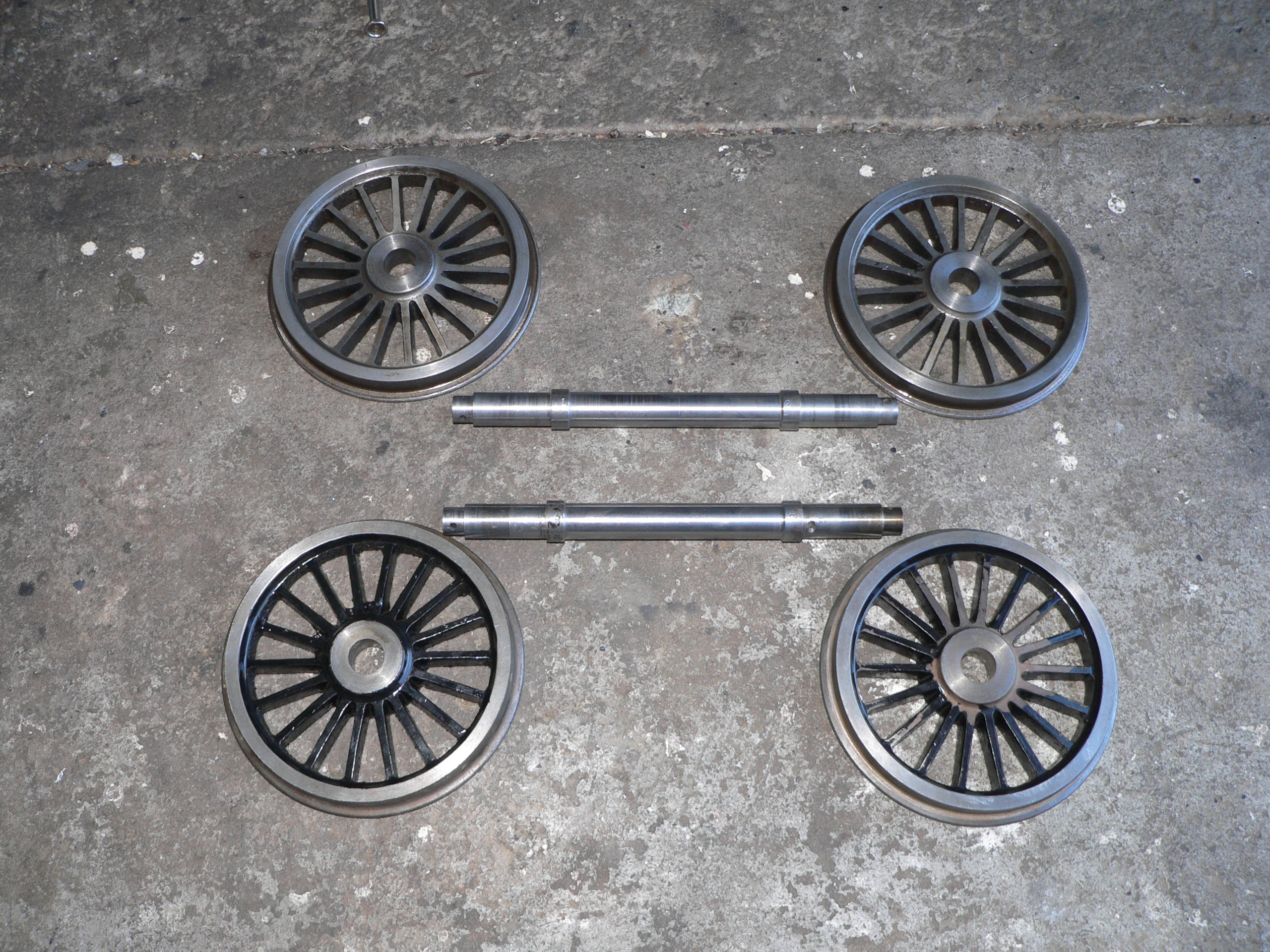
Wheels
A proper fix here would be a shrink or press fit and also keying by a longitudinal pin. This would involve making new axles (including the cranked driving axle) or at least plating the wheel seats on the current axles. This sounds like hard work so I'll try bush mechanics first.
After truing the wheels the procedure is to clean a wheel and axle, apply Loctite 7471 and then 620, then slide the wheel on the axle and hold the assembly in the alignment jig until the Loctite has some strength. The cure rate is slow in the current cool (15°C) conditions which gives me time to position the parts before the Loctite starts to stick. Once positioned in the jig I use a heat gun to warm the parts to about 40°C to hasten the curing. Heat for one hour then move on to the next wheel.
It's difficult to get a full coating of Loctite here because anything on the wheel bore gets wiped off as the wheel slides over the journal. So coating the axle only is all I can do. For a better bond I wipe Loctite 263 around the joint once the wheel is secured on the axle. 263 is very penetrating and with the assistance of gravity and capillary action it fills any gaps here and provides additional bonding. Initial testing shows the bond is very strong. A side-benefit is that the joint can be broken with enough heat and a bit of force. For heat I use a heat gun on full blast.
Each wheel is 14.7mm wide which is less than the AALS minimum of 16mm. However the width across each wheelset is 146mm and the width across the inside of the splashers is only 149mm. So there really isn't any room for wider treads.
Assembly
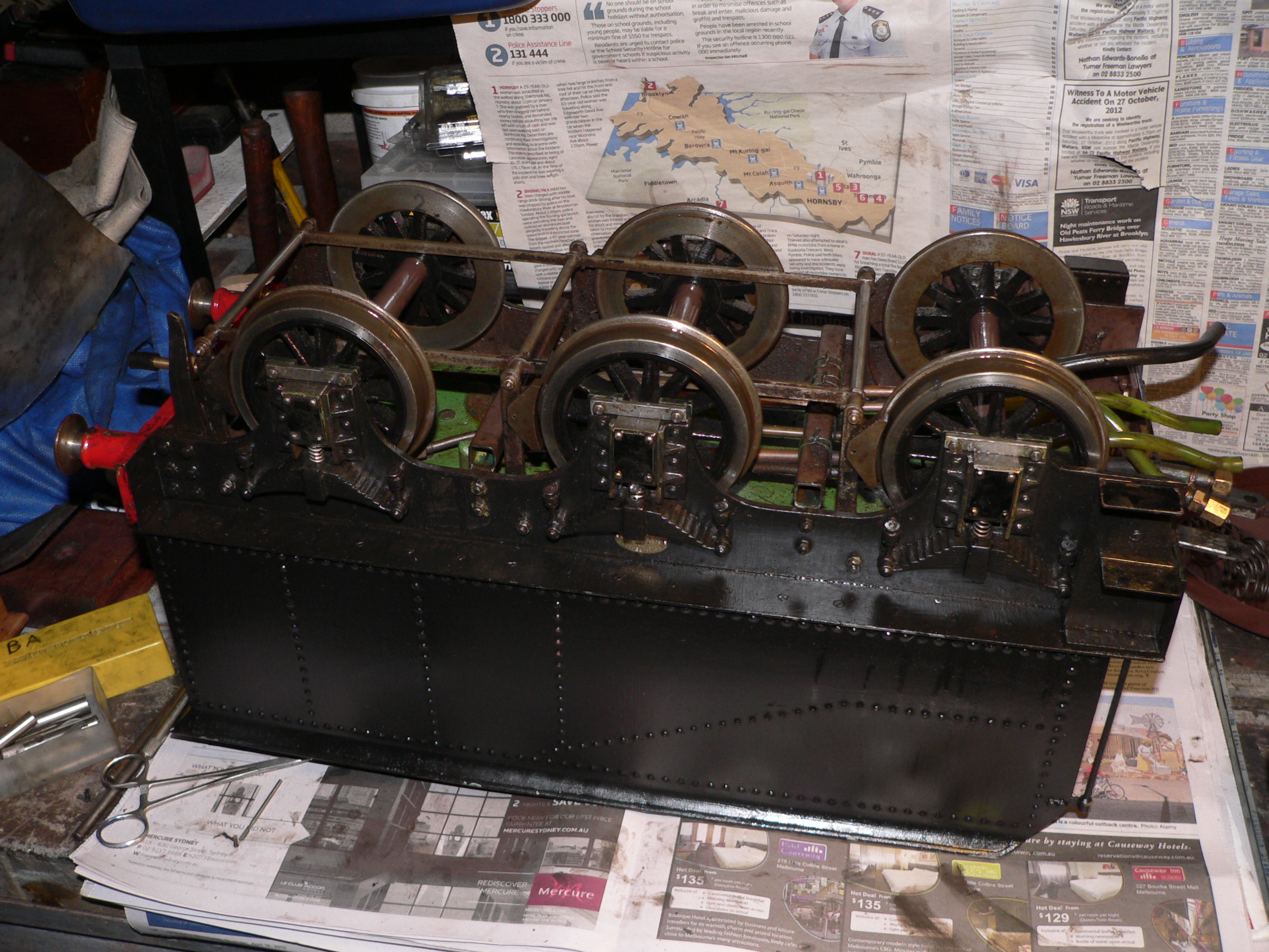
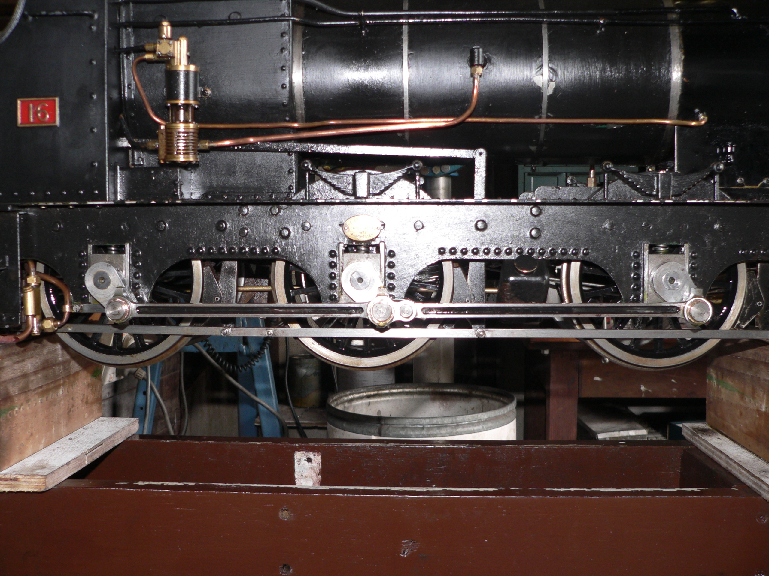
With the wheelsets back in the frames I checked for sideplay. The front axle has 0.81mm, the driving axle has 0.67mm, and the back axle has 0.05mm. The original idea was to centre the driving axle with shims then position the other axles so the backs of the flanges are in line. The back axle is tightly positioned (no sideplay) and to get the flanges in line the driving axle must be pushed to the right and the front axle most of the way to the left.
The axle spacing between 2 and 3 is the same on both sides. For axles 1 and 2 the left spacing is slightly less than on the right. Looks like the front axle is slightly skewed. To fix this would require fixing the axlebox for wheel 1 and extending the left coupling rod. Not a worthwhile option at the moment.
To keep the wheels inline I fitted shim washers behind axleboxes 2 and 3. This keeps axle 1 to the left and axle 2 to the right and the backs of the flanges aligned.
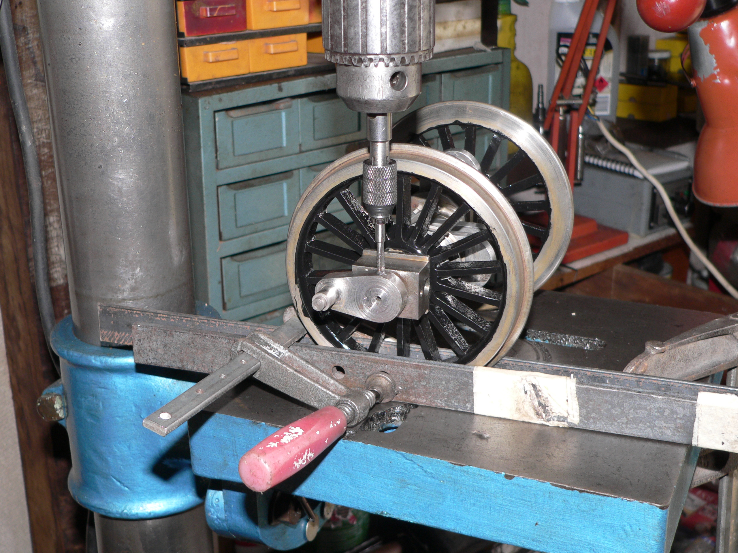
The cranks were secured to the axles by roll pins. These pins didn't handle the load and distorted. The new method is to secure the cranks using Loctite 263 and then tap the transverse hole and fit two M4 grub screws that meet at the centre of the axle. The left picture shows tapping a hole for the grub screw. The right picture shows the cranks fitted to the driving axle after the grub screws have been fitted.
Fitting the left crank to each axle and the right crank to the driving axle is easy as these cranks are aligned by their transverse holes. Fitting the second crank to the coupled axles requires that the quartering matches the driving axle. As before I setup my adjustable coupling rods and positioned the cranks at 45° while the Loctite cured. The transverse holes here should align but might not if there was a quartering error before. The holes did align and the wheels turned freely with the real coupling rods so I tapped the last two cranks and fitted the grub screws. The idea of fitting a Scotch key to each crank has been dropped for the moment because if the pin isn't a tight fit in the hole then Loctite won't be strong enough to resist the force. I'm hoping the current arrangement will suffice.
The springs in the loco and tender are too soft for my liking. Century Spring Corp has a great range of springs and excellent catalogues with all the pertinent details including the spring rate. Shipping from the USA is expensive so I ordered a variety of replacement springs which arrived five days later.
For the tender I'm using hard springs at the back and softer springs for the front axles. This is because the front of the tender takes the weight from the footpegs and is vertically restrained by the draw bar. So the weight on the front of the tender is transferred to the back of the loco. The softer springs at the front keep the wheels on the rails and let the rear axle on the loco take most of the weight. Because of this the loco will have hard springs for the back axle and softer springs for the front two axles.
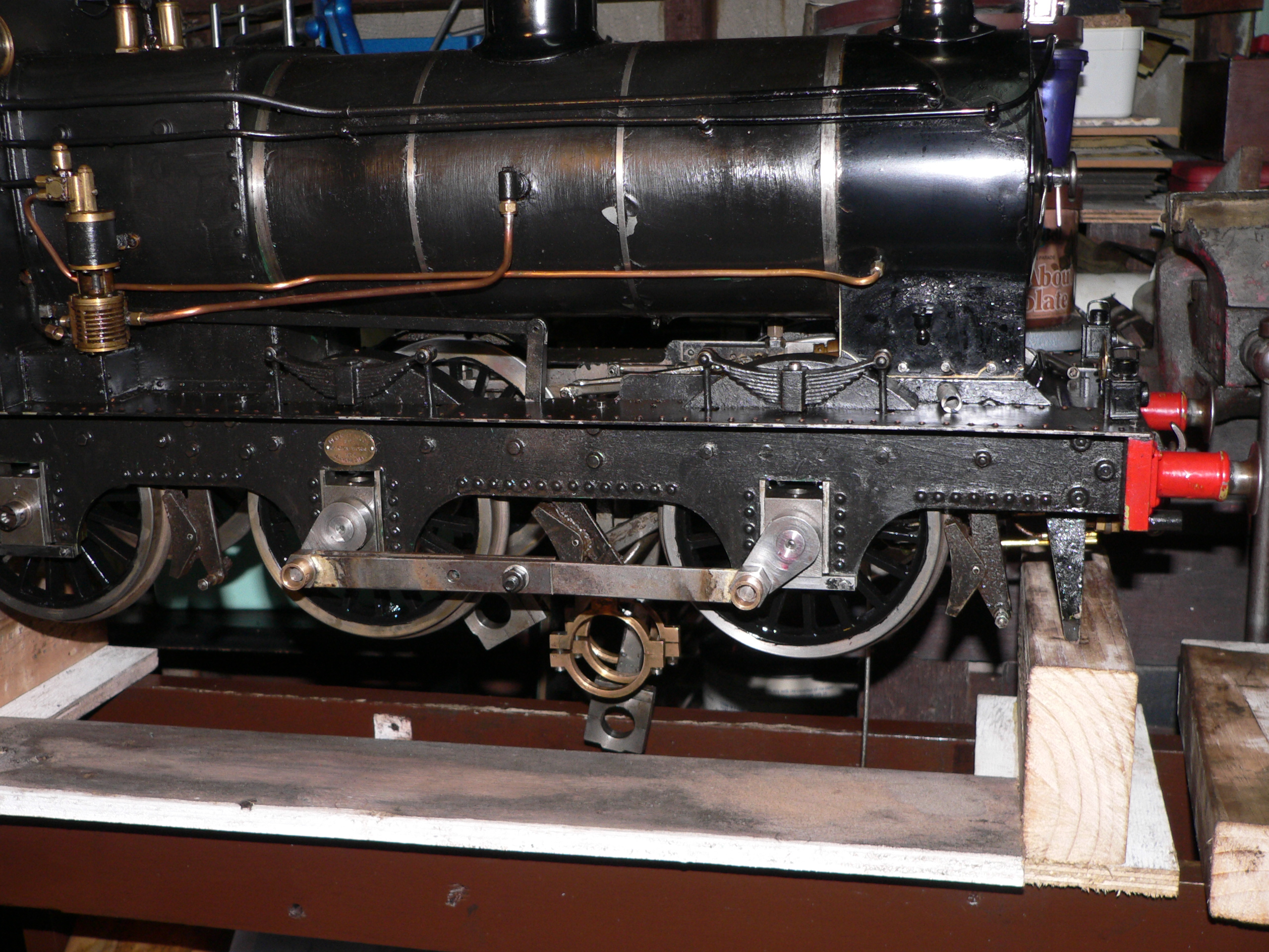
Fitting the coupled wheelsets is easy and I made a small jack with a central screw so I could push the wheelsets up and check the springs were deflecting equally. Fitting the driving axle is another story because I had to fit the eccentric straps and connecting rods. There is a critical point when lifting this axle when the straps can be fitted and the screws are just accessible. Presumably it was all assembled originally before the boiler was fitted. Once the axles were in place I fitted the brake gear and pipework that lives under the axles.
Previously the coupling rods rotated against the cranks. I fitted some brass shim washers to keep the rods off the cranks and also reduce the sideplay. This required machining the outer face of some bushes so each bearing had about .005" sideplay.
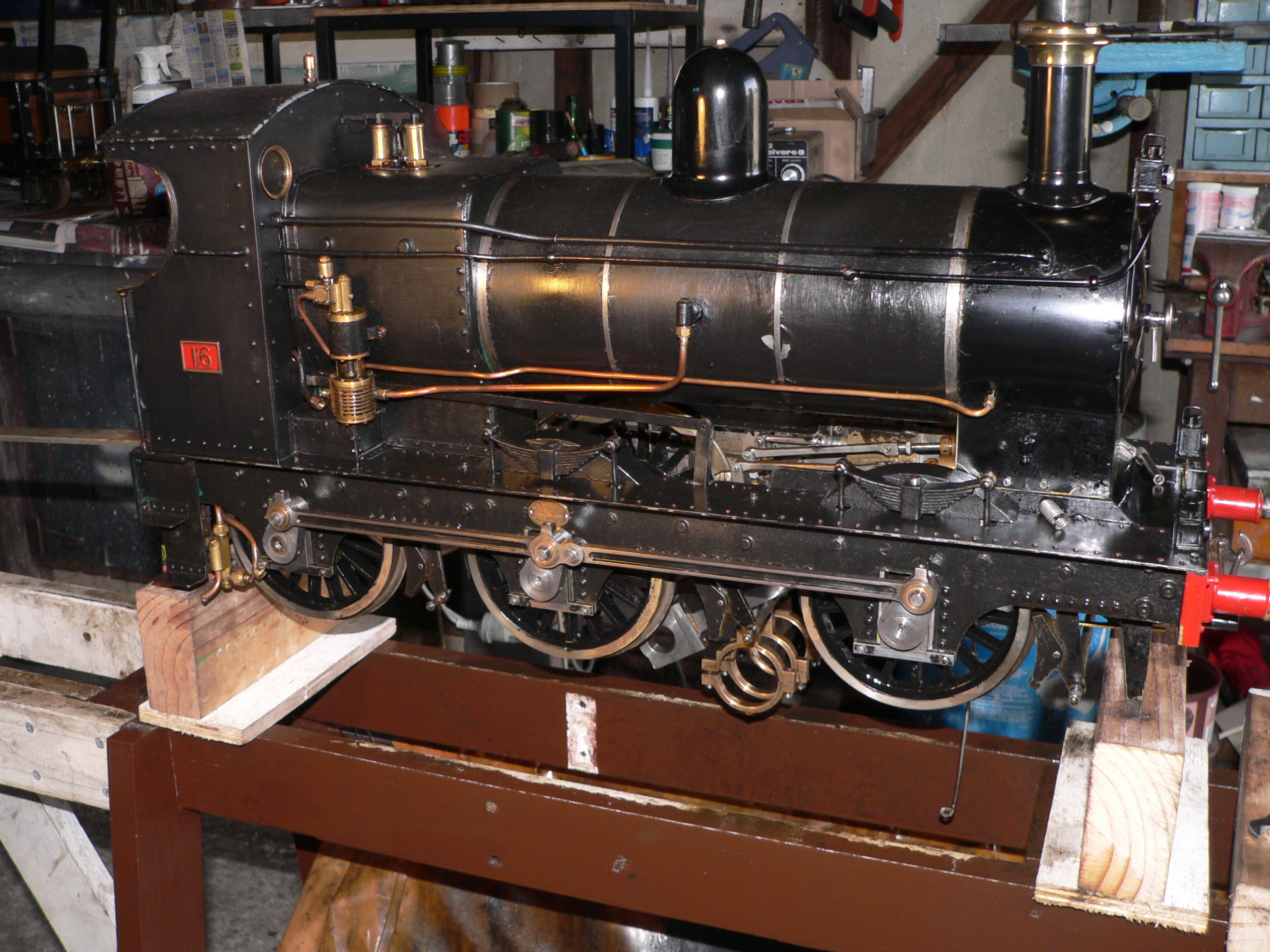
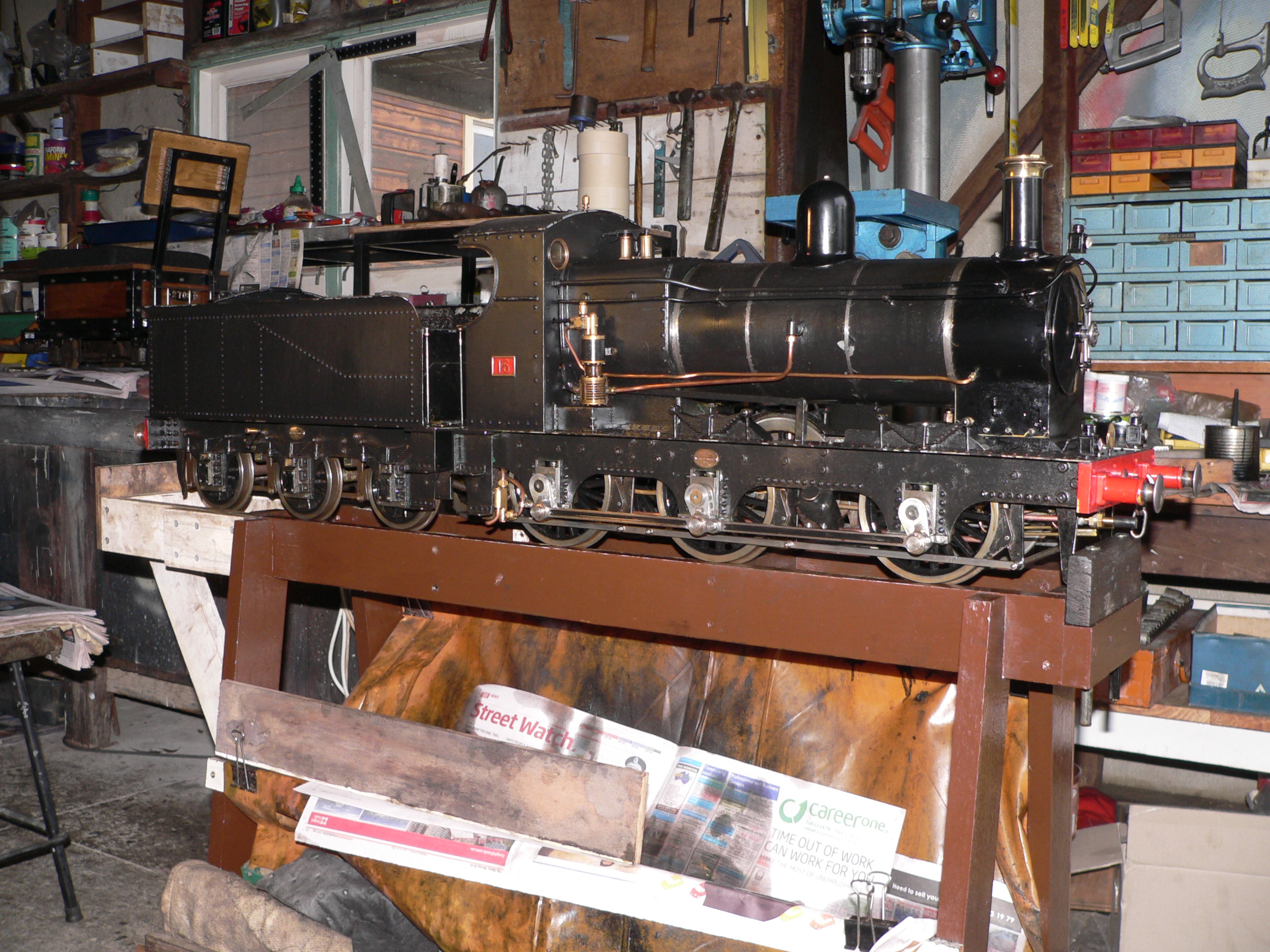
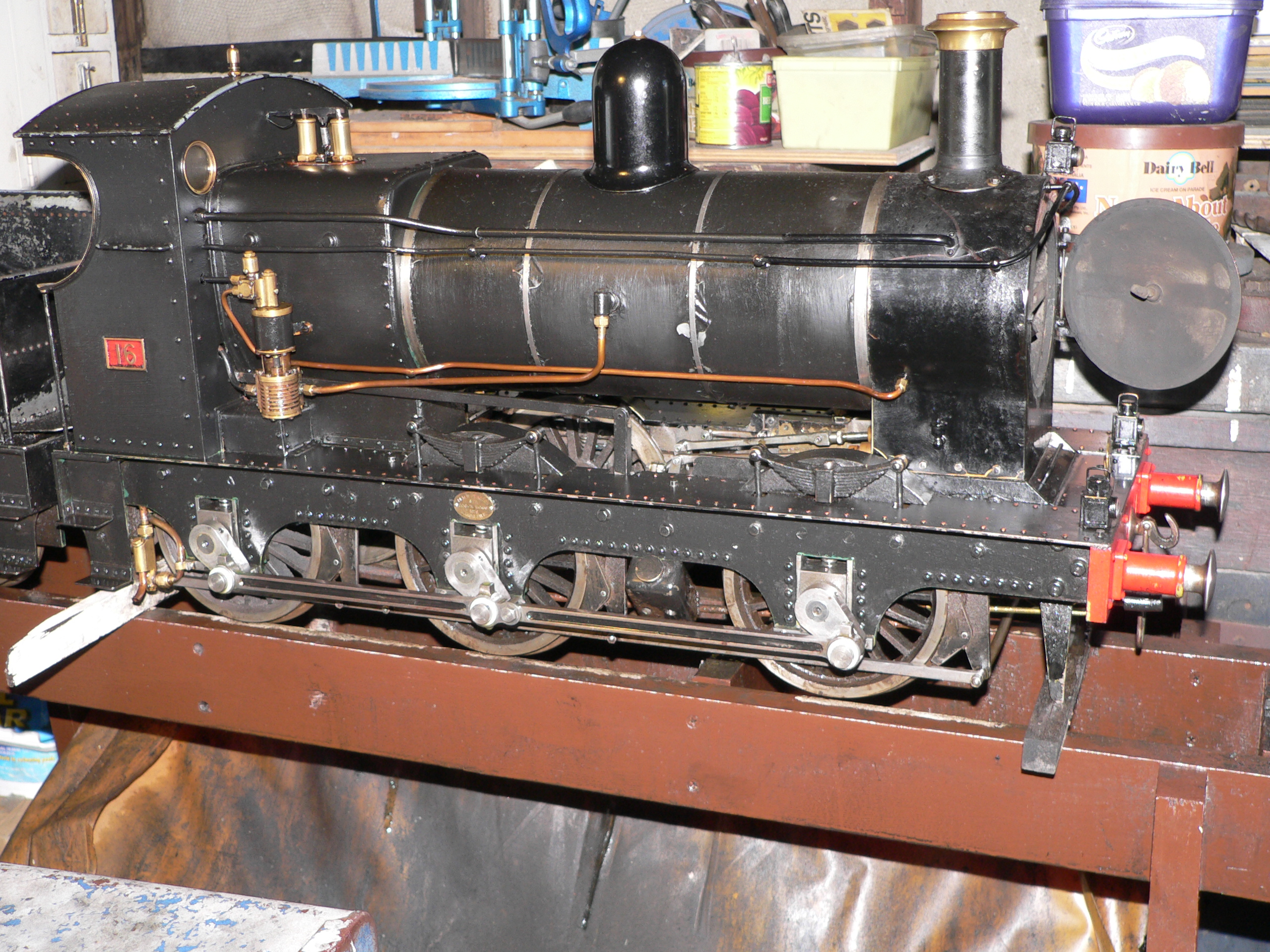
Now the loco is finally back together and ready for a test. The height match between the engine and tender is good and the loco sits well on a flat smooth bit of track. How well it tolerates bumps and twists remains to be seen. How tolerant vechicles should be of track faults is a bit of a moot point as I've never seen any 5" gauge track specs relating to twists and undulations.
Results
After three test runs the loco is still intact and all repairs have been successful. The wheels are still firmly fixed to the axles (done with Loctite only) and the cranks are still tight on the axles (done with Loctite and grub screws). The loco has been driven over some faulty trackwork and even this hasn't cracked the wheels off the axles.
The new springs are also working well. The engine wheelbase is fairly short (about 16") and the tender is slightly less so even if there was no springing it would still take seriously bad trackwork (humps and twists) before this would cause a derailment. The loco sits upright now and doesn't wallow even when under full power. This seems much better than before.
All three tests have included pulling maximum load trains and running times have been at least six hours. This has been a good test for Loctite which has passed with flying colours.
As an aside, for these tests I was burning coal instead of char or coke. The results here were mixed. For the first test I used Clarence coal which was slightly damp. This coal produces lots of ash which blocked the tubes and spark arrestor. The heat output was less than expected, perhaps due to the dampness. Once great feature of this coal is that the ash doesn't melt and there is no clinker.
The second test was done with Gunnedah coal which creates lots of flames and smoke. The heat output was great but this coal created lots of clinker and hard deposits on the tubes. Also, this coal burns with smoke right down to the end so it was hard to get a bed of hot coals. I ended up with a firebox full of clinker with flaming pieces of coal on top.
For the third test I had a gap at the bottom of the spark arrestor so there would still be a draught even if the arrestor blocked. Also I tried a "brick arch" made from Kao-board. For this test I ran on a mix of Clarence coal and char. The brick arch lasted until I hit it with the fire iron and dislodged it. As it was blocking the tubes I had to break it up, remove what I could, and mash the rest into the fire. The loco ran well (perhaps better) with the arch in place. Without the arch it still ran well all day. It did seem to use more coal without the arch. The fire did clog up occasionally (probably when the fire was too thick). It was always easy to break up the fire and keep the loco going.
Clarence coal does produce lots of ash which can be a problem. The lack of clinker makes it better than many other coals in my opinion. I do think that the small size of the firebox stops the volatiles from burning properly and this means most coals just don't work well here. The Kao-board arch should help increase the burning time before the gases hit a cool surface. Another problem with coal is the smoke which is hard on the driver and not appreciated by most passengers. Sometime in the new-age future we'll all be forced to convert to gas firing. Yuk.
Coupling rod bearings
The bronze bushes in the coupling rods were worn. Rather than make replacements in bronze I decided to try some bearing plastic from Vesco Plastics Australia. The product is called Vesconite HiLube and is recommended for low speed applications. Heat could be a major problem but as I'm sure the crankpins will never exceed 70°C I'm well below the temperature limit for full loading.
Vesconite HiLube is a white plastic and probably PTFE impregnated. The maximum PV (loading times speed) varies depending on lubrication and even when dry it well exceeds the calculated value of the loco running at maximum tractive effort at 10kmh. A big advantage here is that it won't score the journals if run dry for extended periods. This sounds much better than bronze.
I bought a length of 16mm rod. Machining was easy. Because the bushes have thin walls I had to bore and ream the bush first and then support the rod using a polished spindle in the tailstock while machining the outside. All bushes are 3/8" ID and the OD varies from 11.9mm to 13.2mm to suit the holes in the coupling rods. The depth varies from 11.0mm to 11.9mm to suit the crankpins. I did ream the bushes again once pressed into the rods.
The initial test was done hauling two carriages and one passenger and keeping the loco above 8kmh for about 8km with a stop halfway for coal and water. The bushes are still as good as new and the wheels spin freely with no slop.
The pictures below show machining of a bush and the loco with its new white bushes installed. Admittedly the white plastic flanges don't look as good as the bronze bushes. C'est la vie.

Last modified 2013-11-17
| Contents | Prev Next |