
5" gauge NZ logging loco
|
5" gauge NZ logging loco |
|
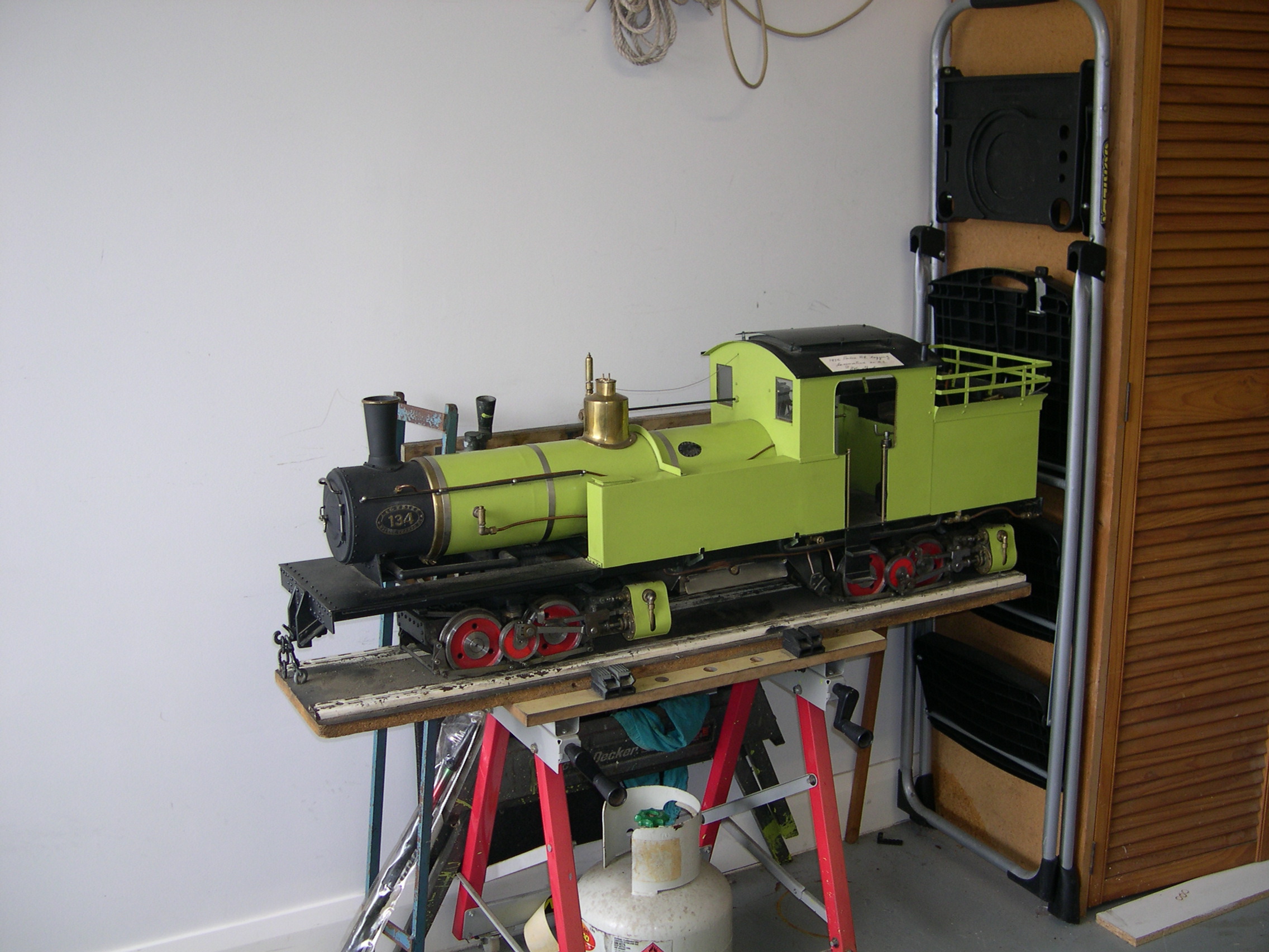
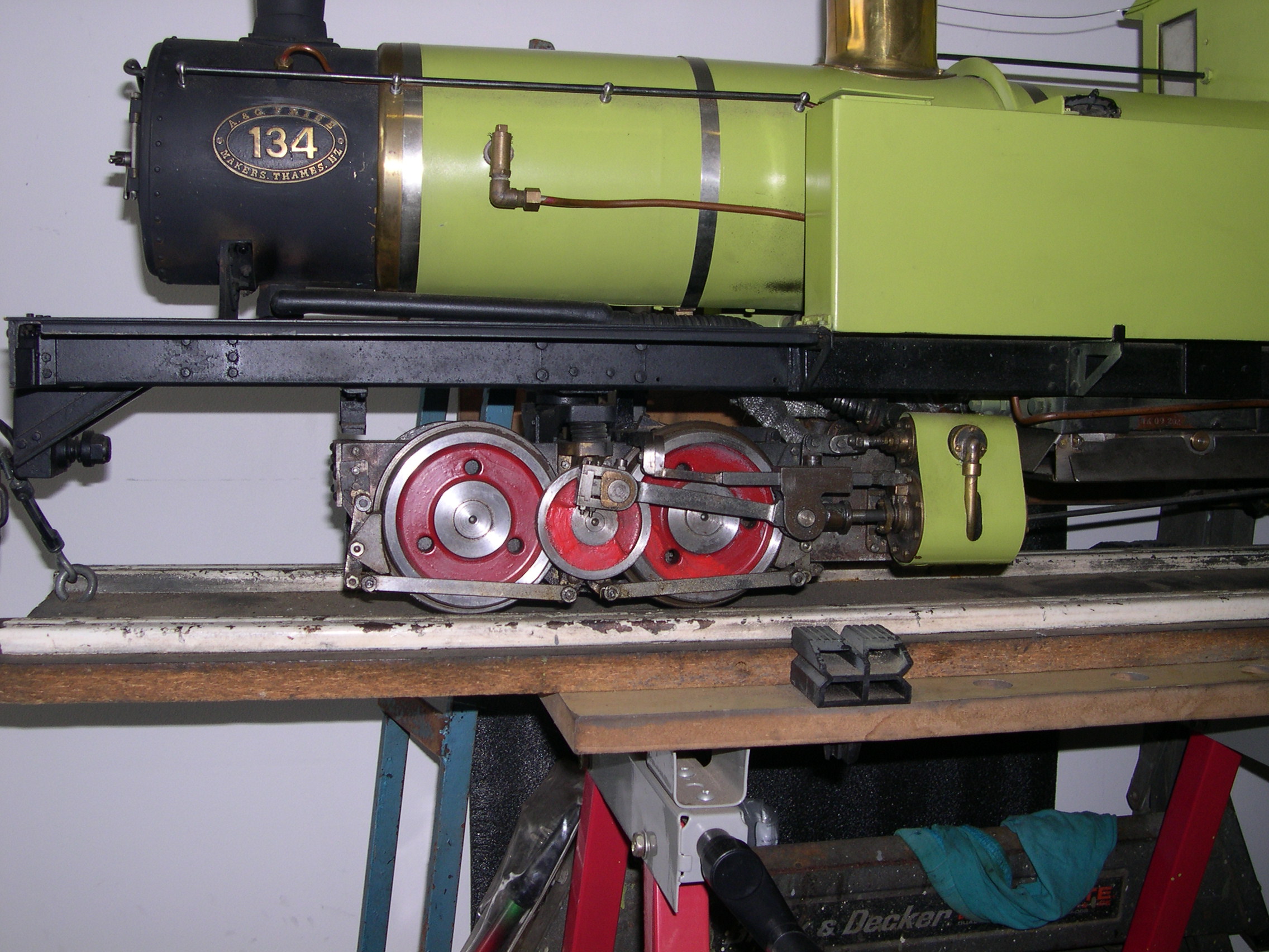
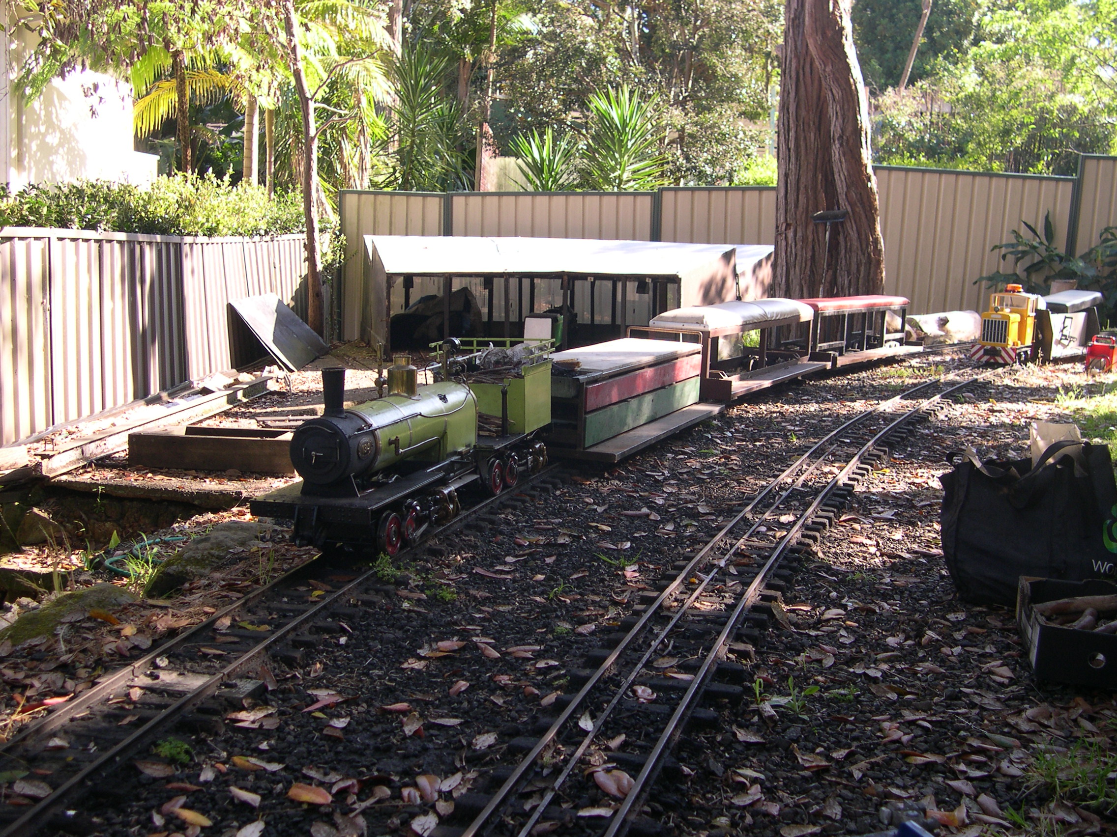
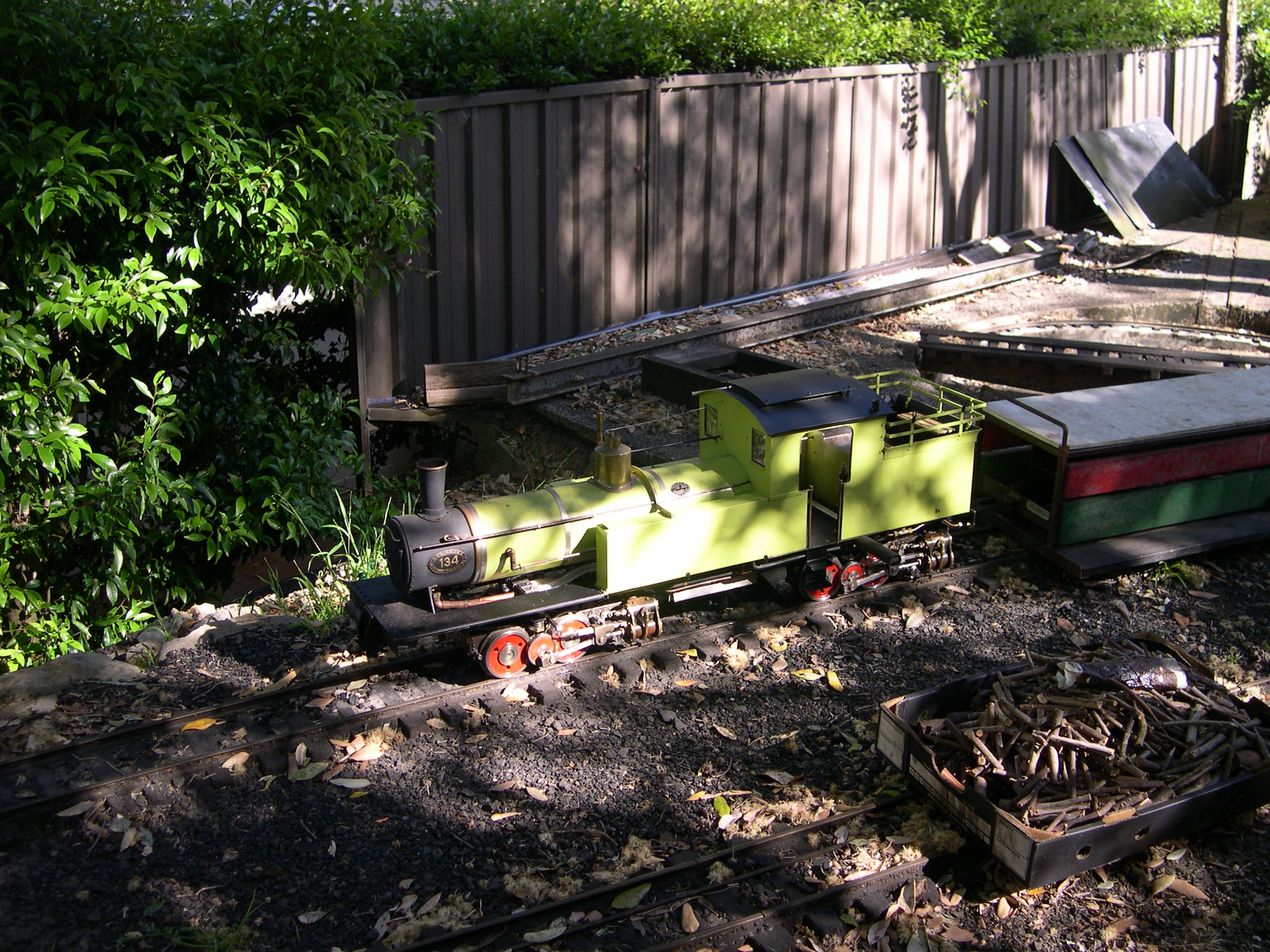
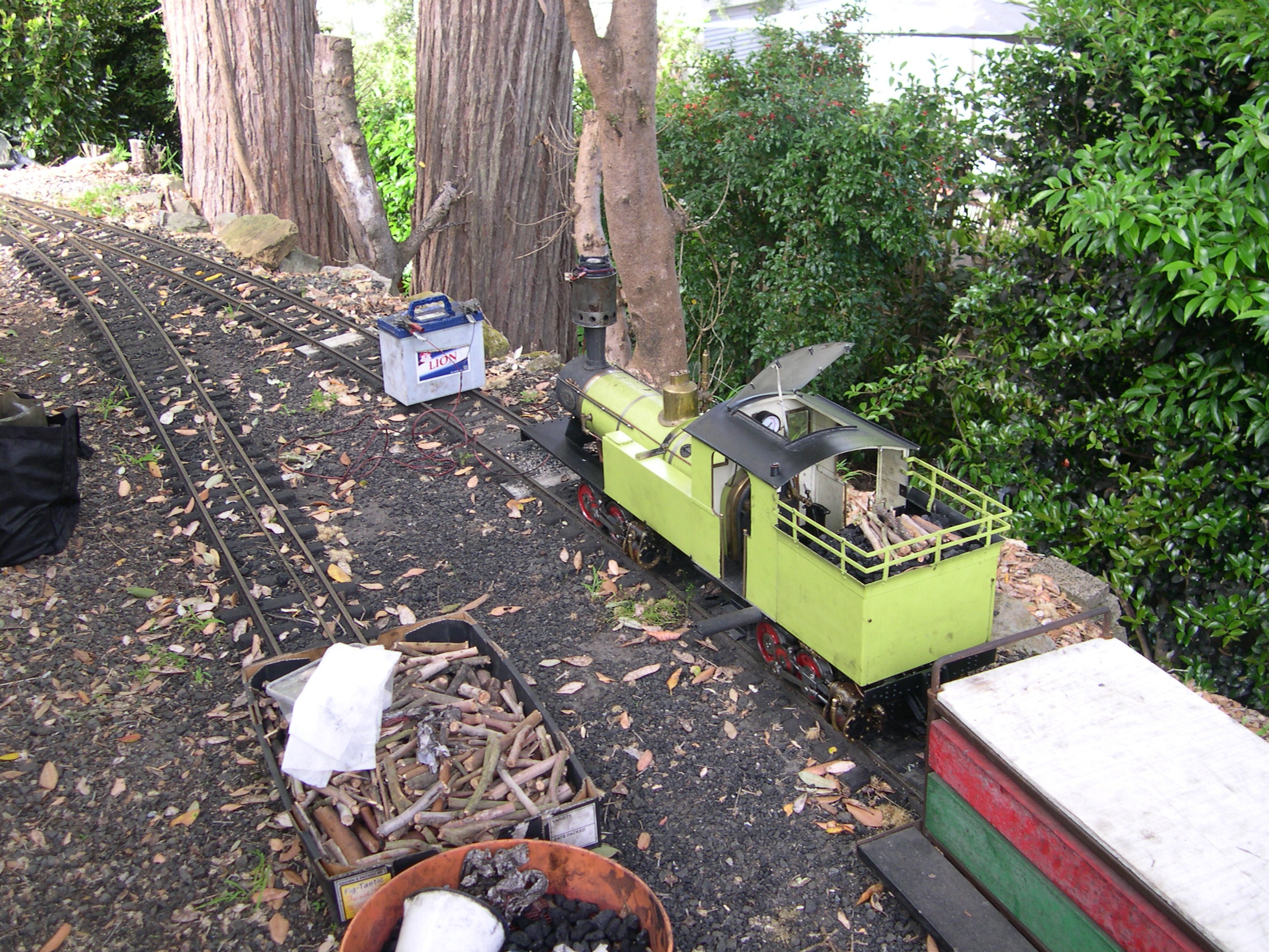
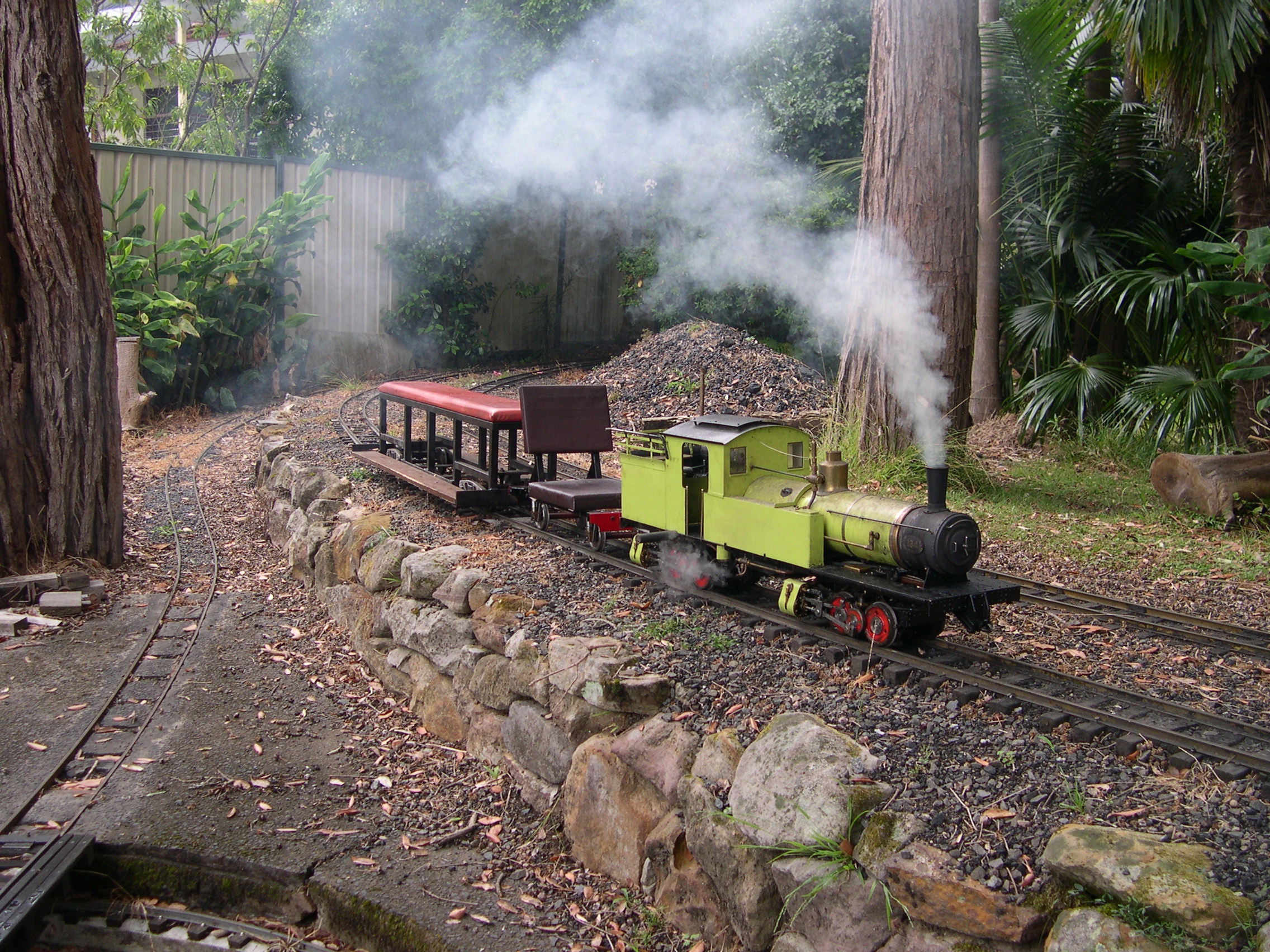
This 5" gauge model was built by Bob Short in Sydney but was never steamed or run on a track. Apparently some air testing was done. Bob has spent many years making model ships, cars, and trains and the detail in this model highlights his expertise. Unfortunately Bob passed away on 2024-02-15. Luckily I did have the loco running well before that and did show him videos with the loco in steam and running on a local track.
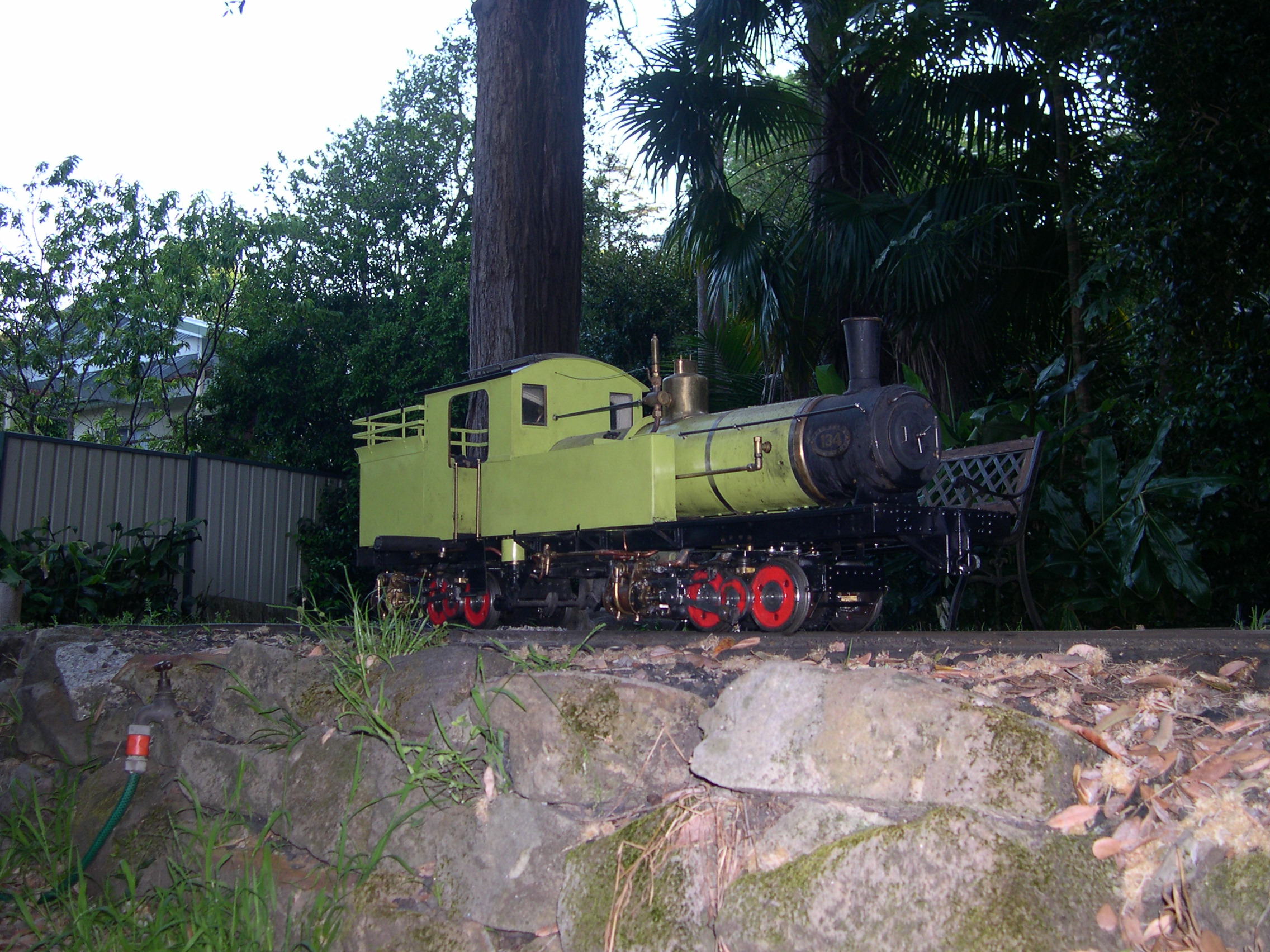
The real loco was made by A&G Price Ltd in Thames, Auckland, New Zealand for the Marlborough Timber Company. Only one such loco (type Ar, builders number 115) was ever made. Sometime in the 1950s (possibly after the loco was scrapped) the builders number was changed to 134 in the Price records as 115 is recorded as an NZR class Ab loco. The builders plates on the model use 134. There are a few grainy photos but few details of its life. Luckily New Zealand Rail and Locomotive Society has the drawings and some records of this loco including a high-quality builders photo. The loco is a Meyer locomotive with both bogies powered. As far as I can tell this is the only geared Meyer loco ever built. The pistons drive crankshafts with gears to the axles. The steam from the rear bogie exhausts via a small chimney at the back of the cab. How well the real loco steamed is unknown but many Meyers were reported to be poor steamers.
I first heard this loco was for sale on 2022-01-18. I subsequently visited Bob's wife to see the loco and other gear for sale. Finally I bought the loco on 2022-03-25 and have been working on it since then.
Obviously the goal was to get this loco fully operational. But I was prepared to end up with less if fatal problems were encountered. Perhaps it would just be a display model or only run on compressed air on a stand. Many unfinished locos do have serious problems which is possibly why the original builder gave up. Although it is an excellent model it did require some work to make it an operational model. There were some design issues to contend with and other shortcomings to overcome. The loco is called Arnie because like Arnie it'll be back. Also, it's the Terminator because I'm sure it will be the end of me.
Clicking on any picture here will show the full-size version. Use the browser back button to return to this page.
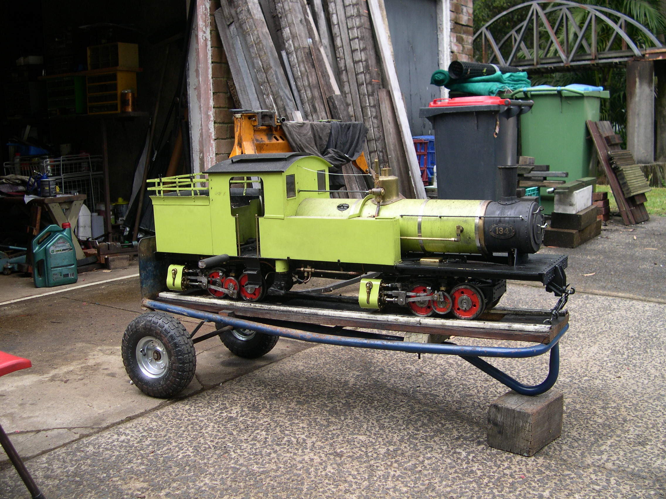
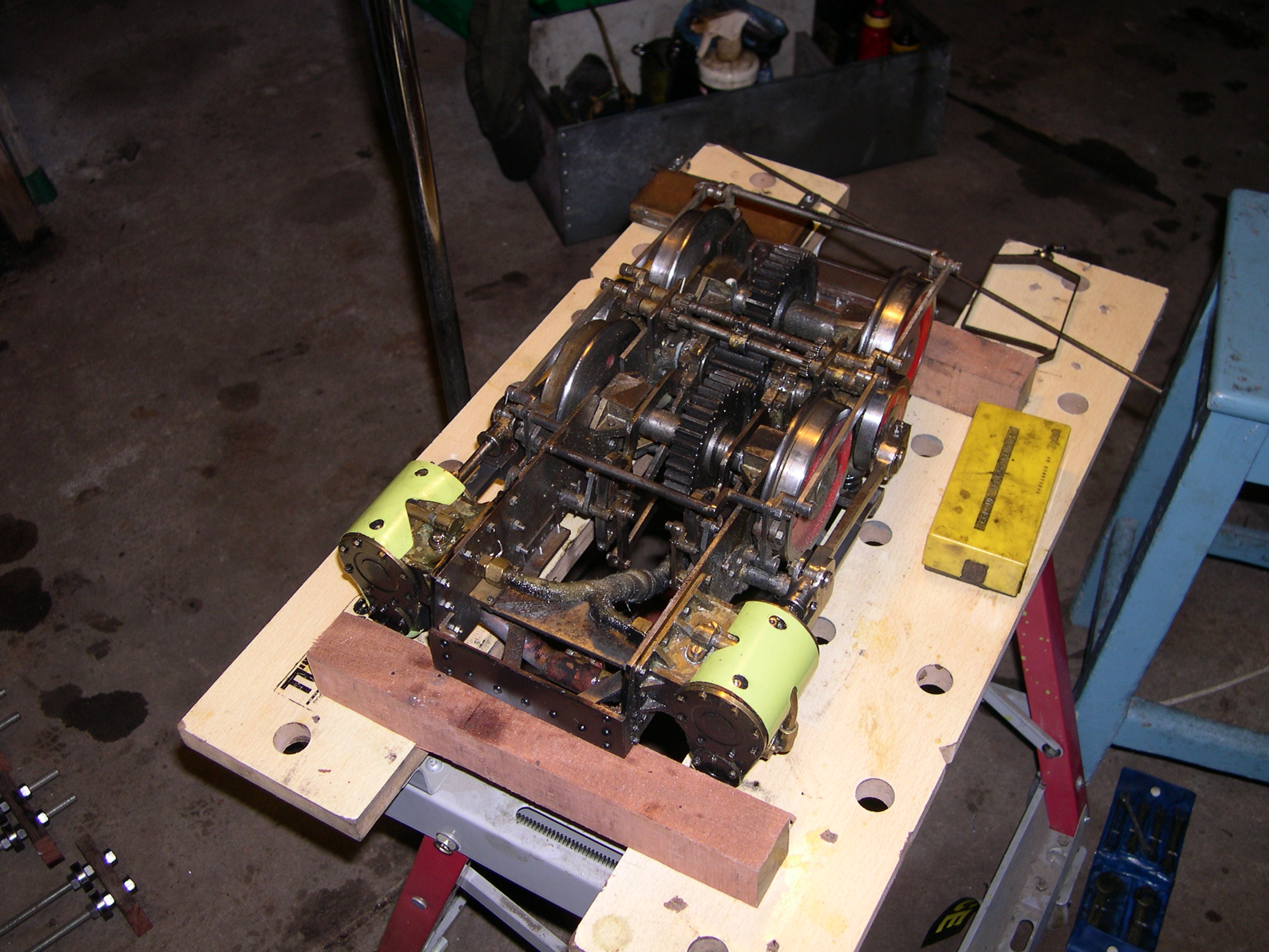
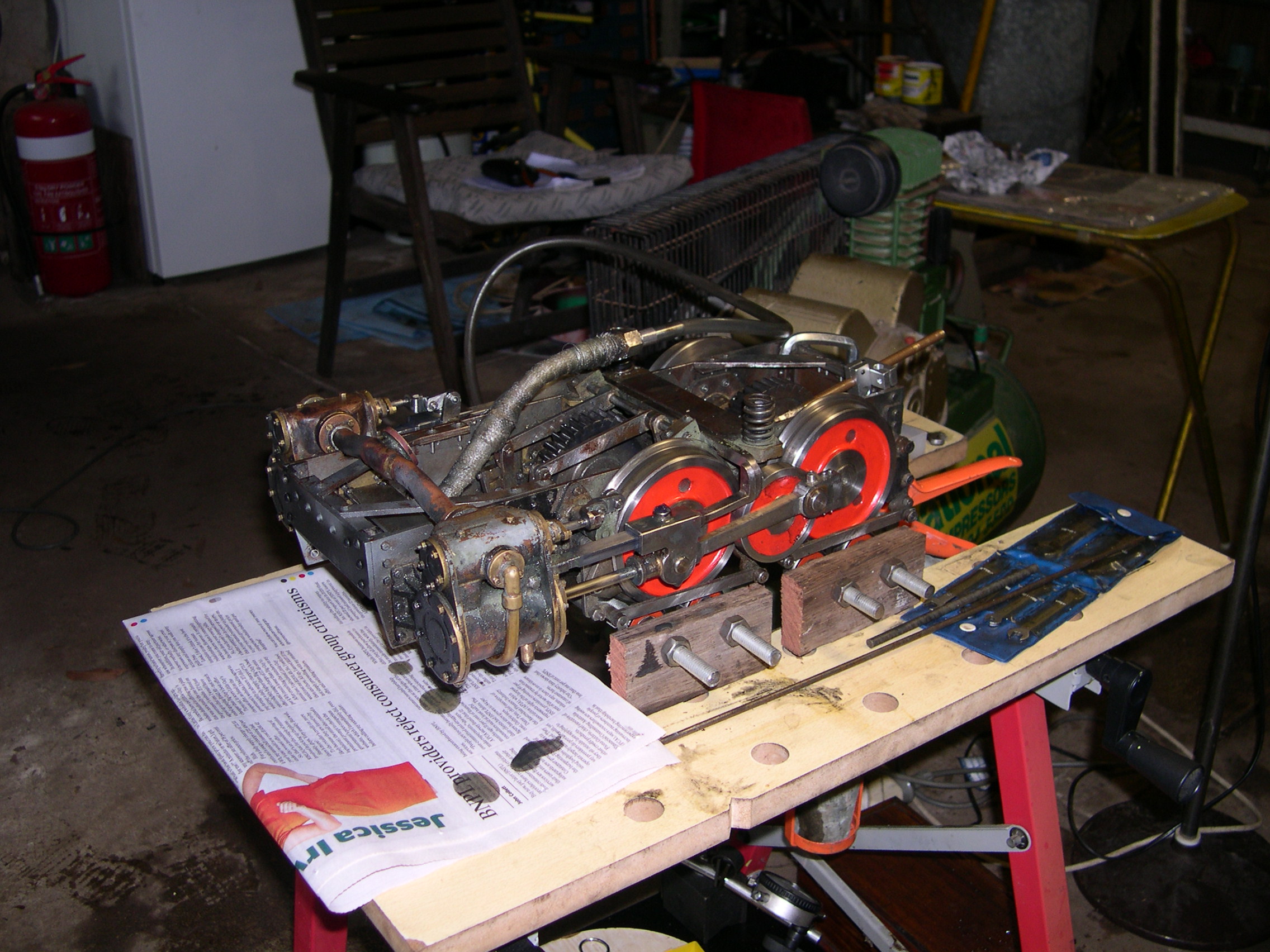
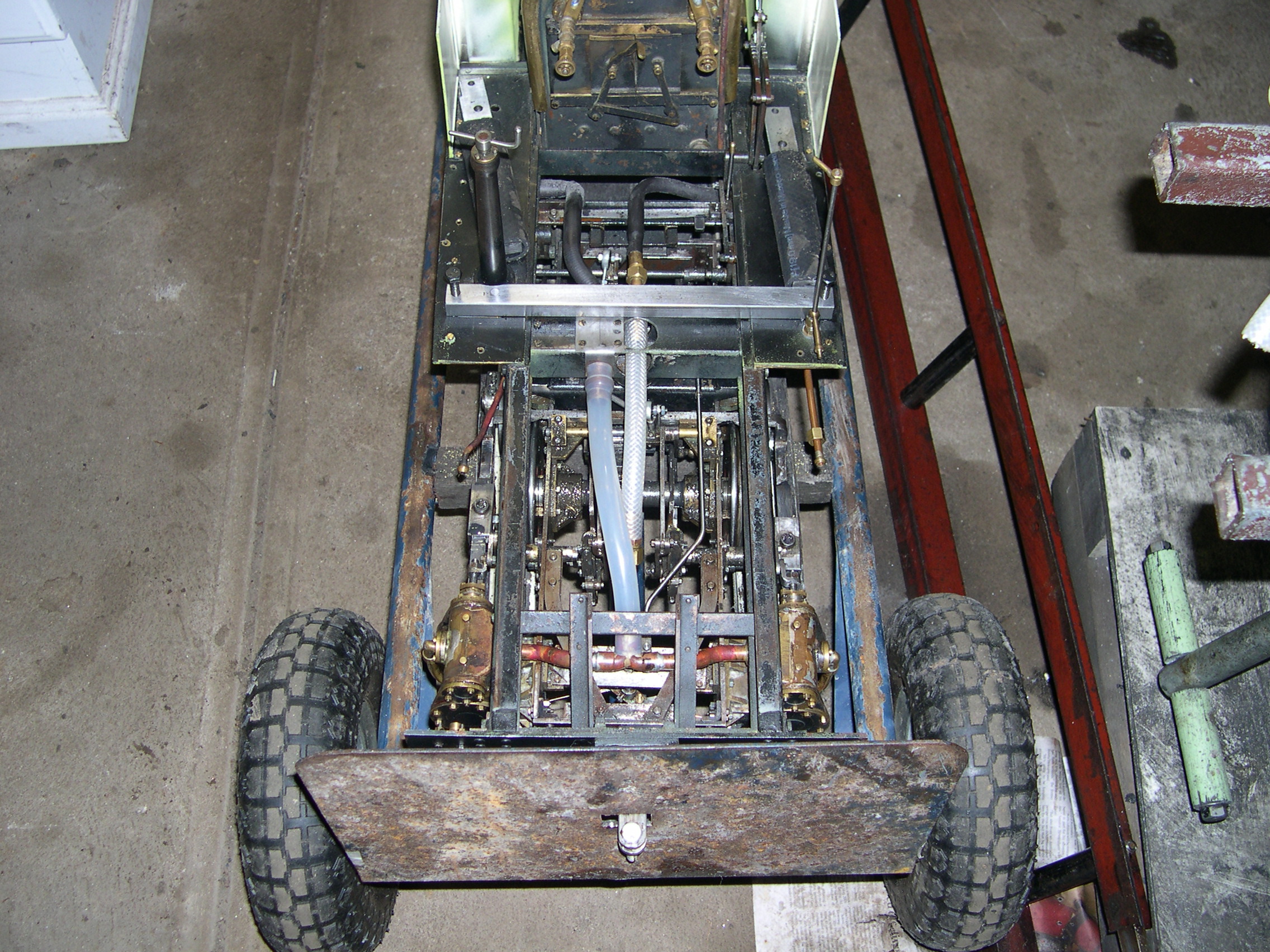
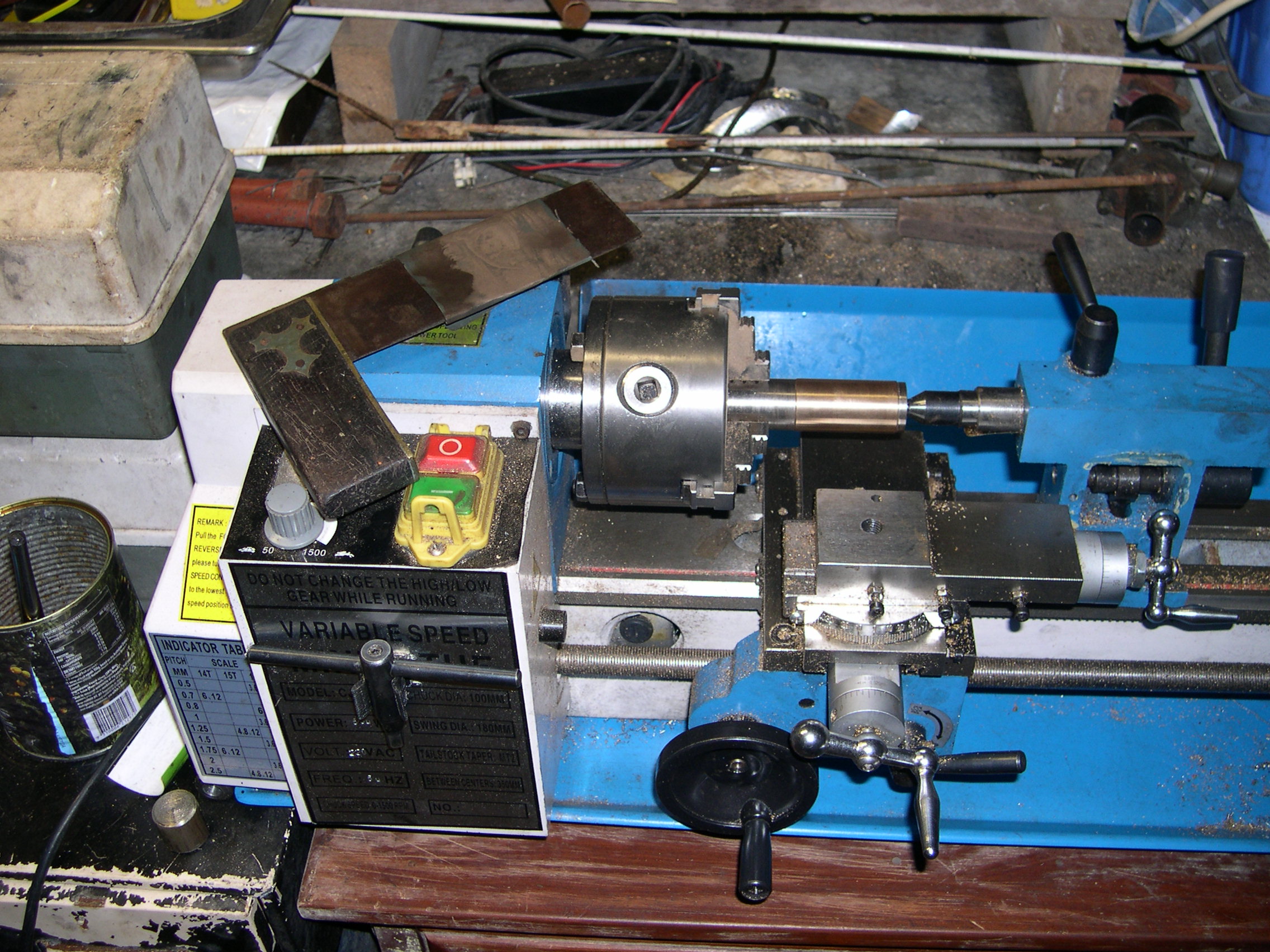
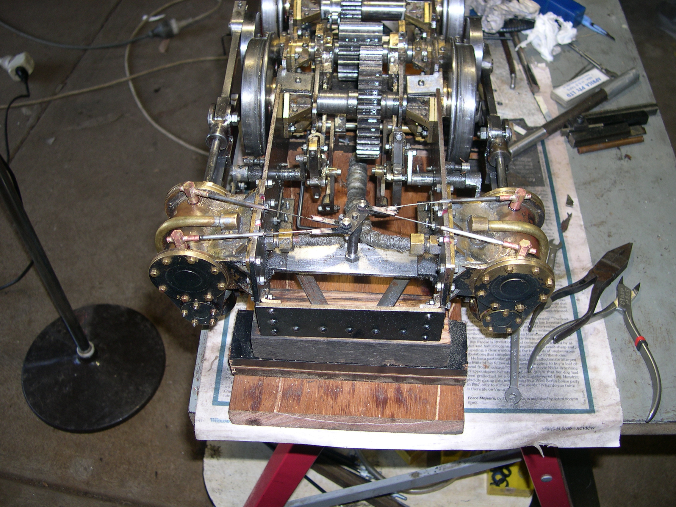
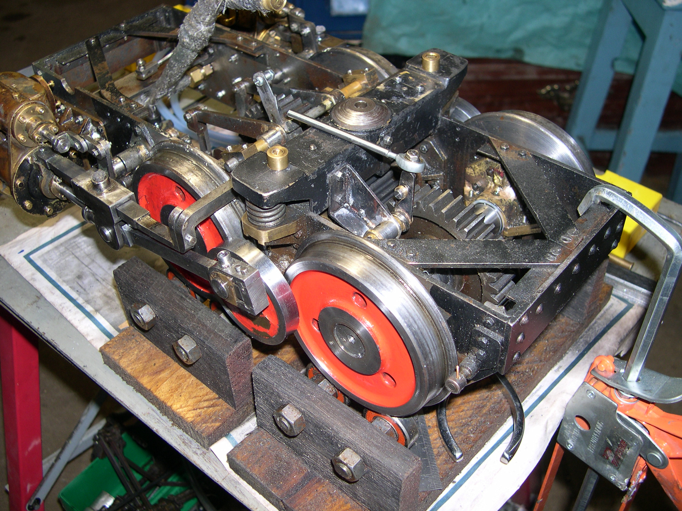
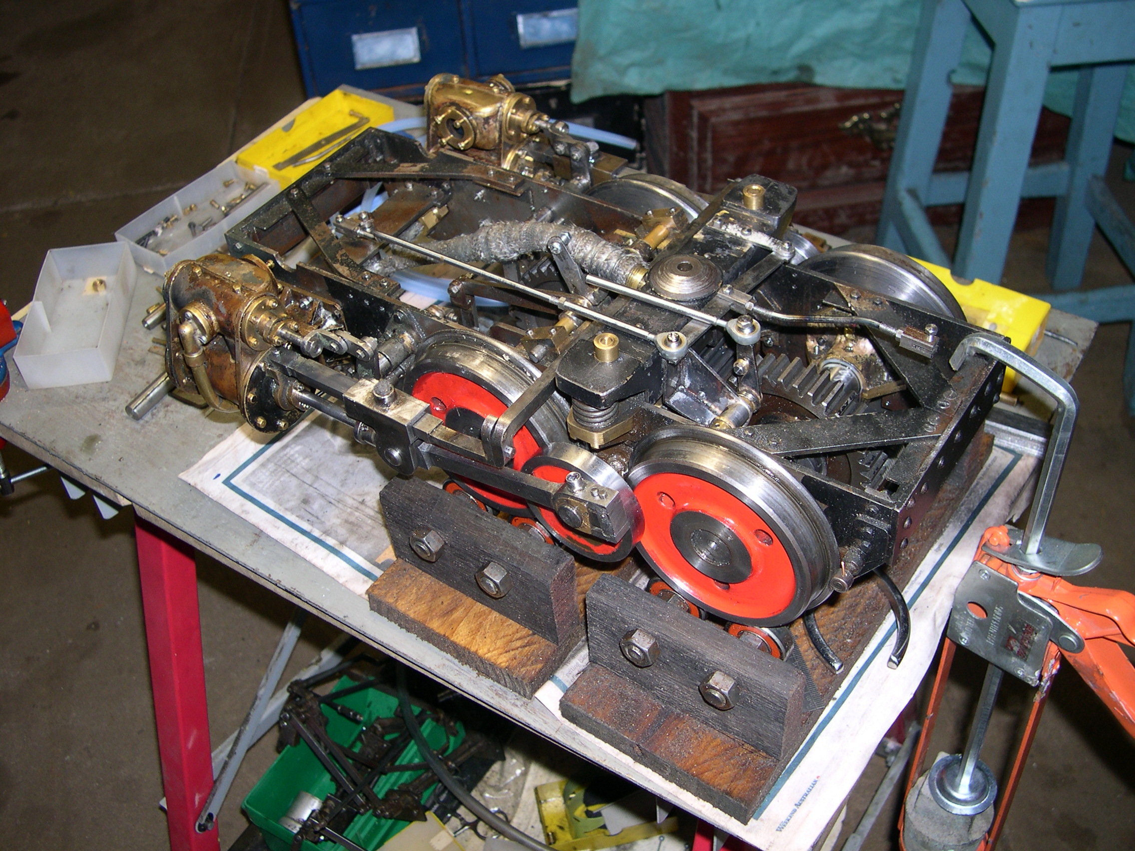
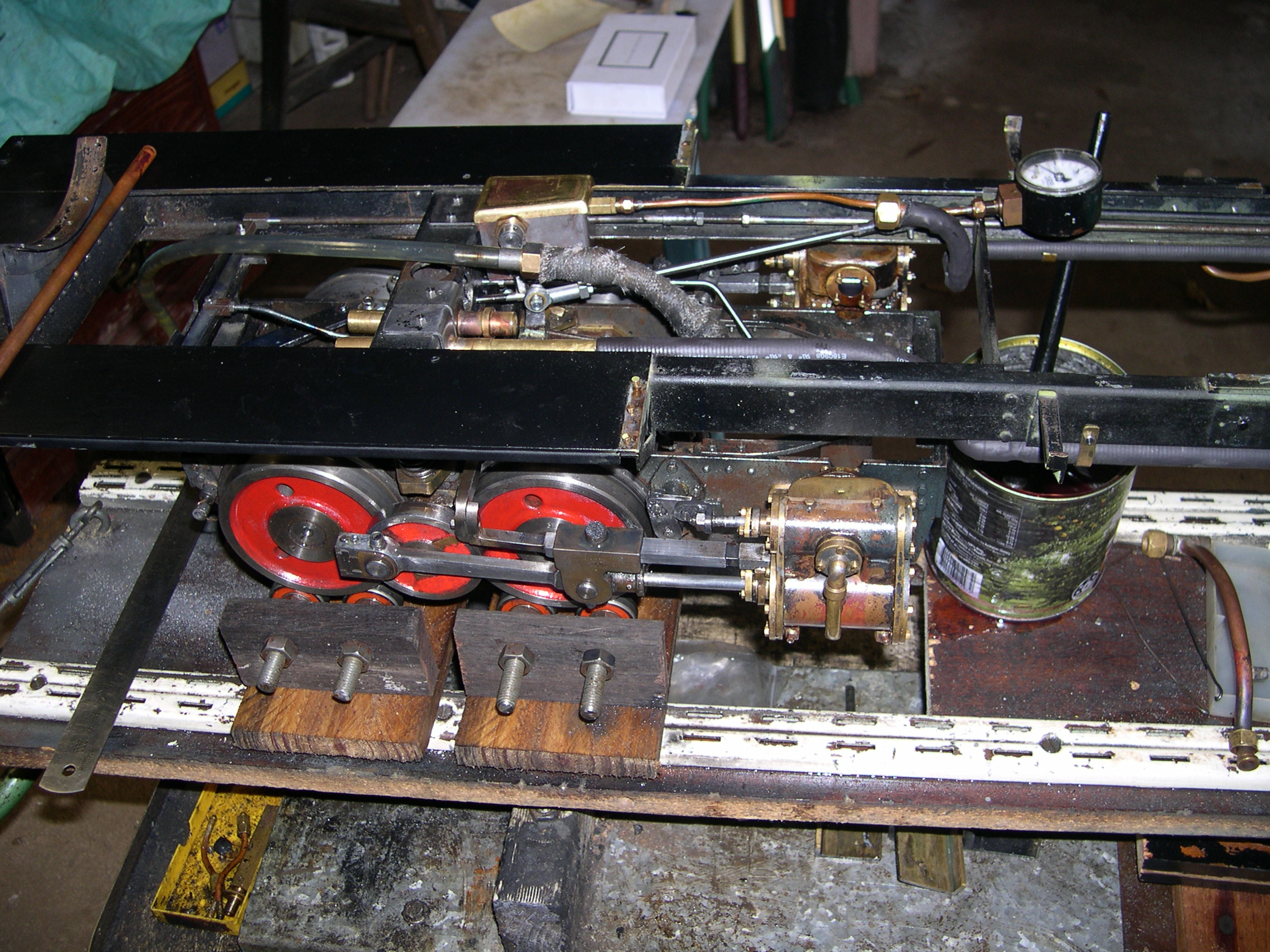
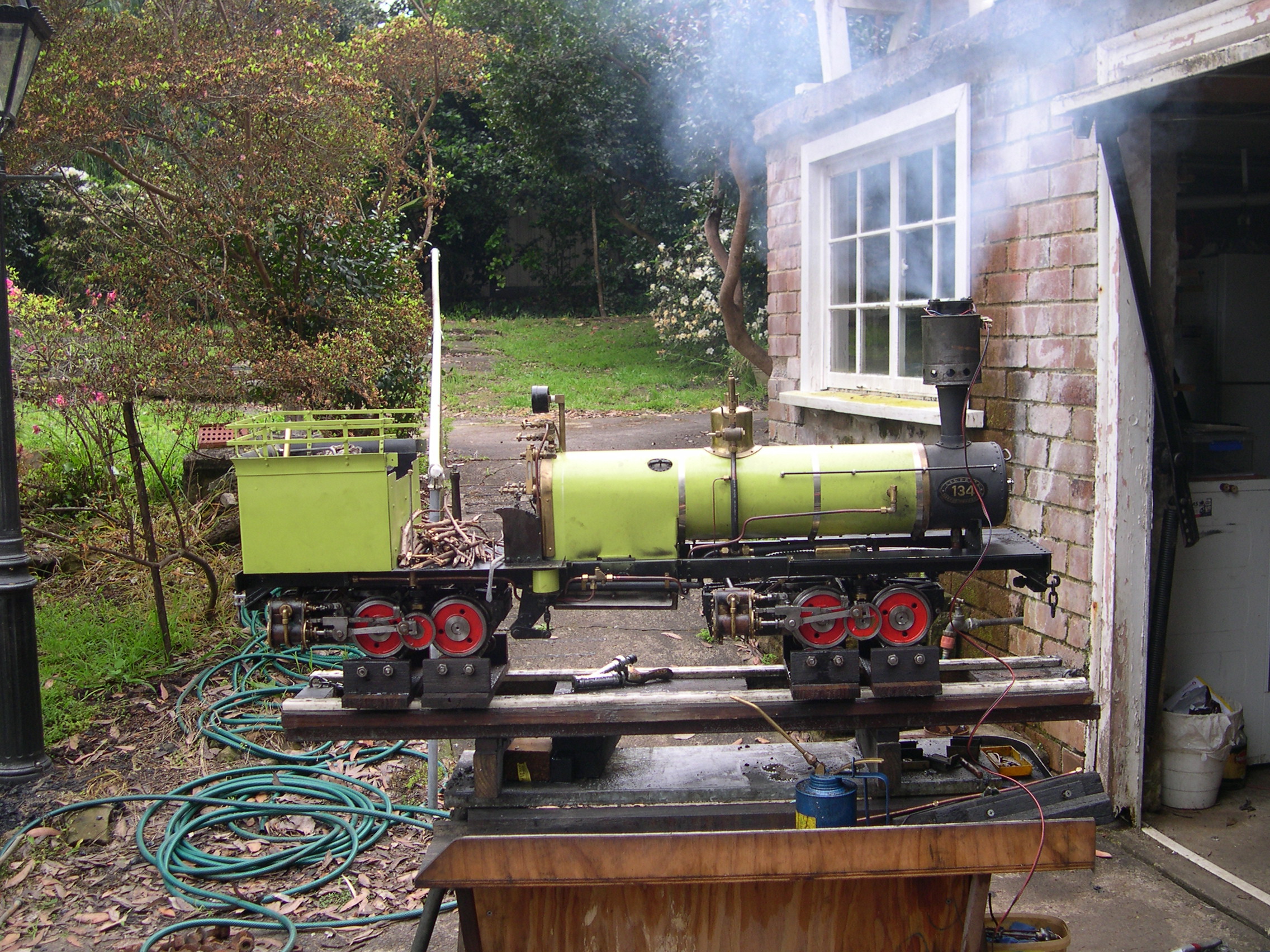
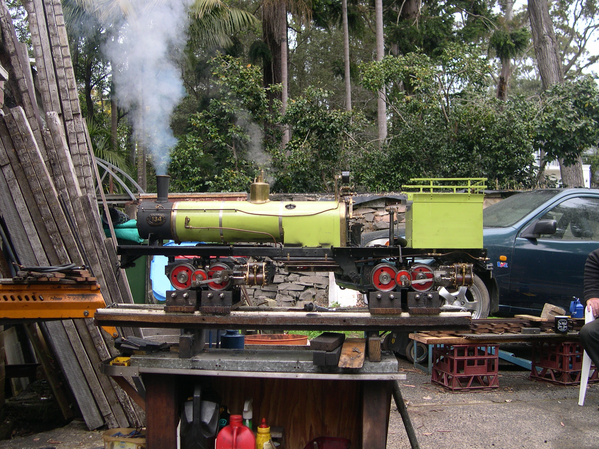
Here is the loco up on blocks for a test using compressed air. Prior to this I'd put oil down both chimneys but unfortunately most just leaked out. The leaks here will have to be fixed.
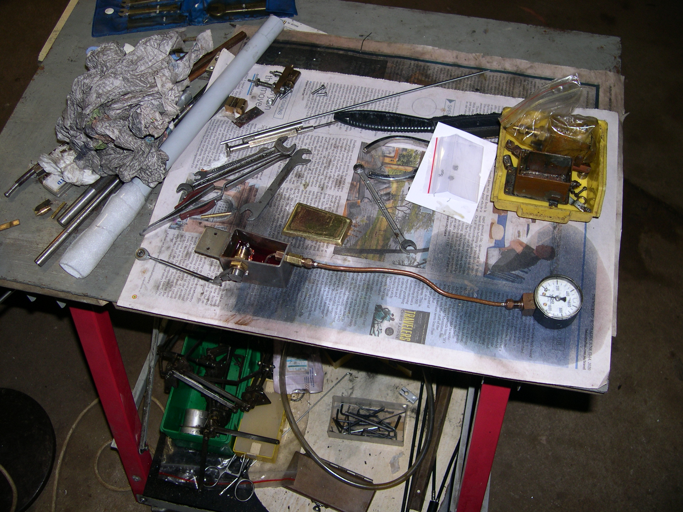
The boiler has a number (NK09202) which indicates to me it has had a squeeze (hydro pressure test) at least. So it should be safe to pressurise the boiler with air for this test. At first I supplied air via the clack valve for the injector. Then I found an adaptor Bob had made so I could pump air (or water) into the boiler via the auxiliary feed pipe from the hand pump in the bunker.
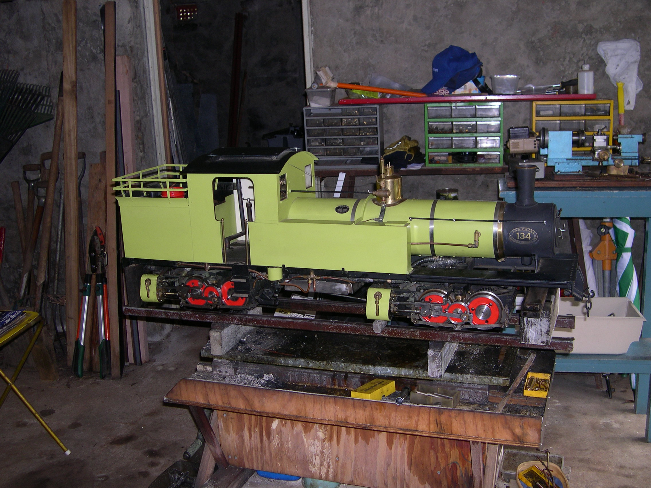
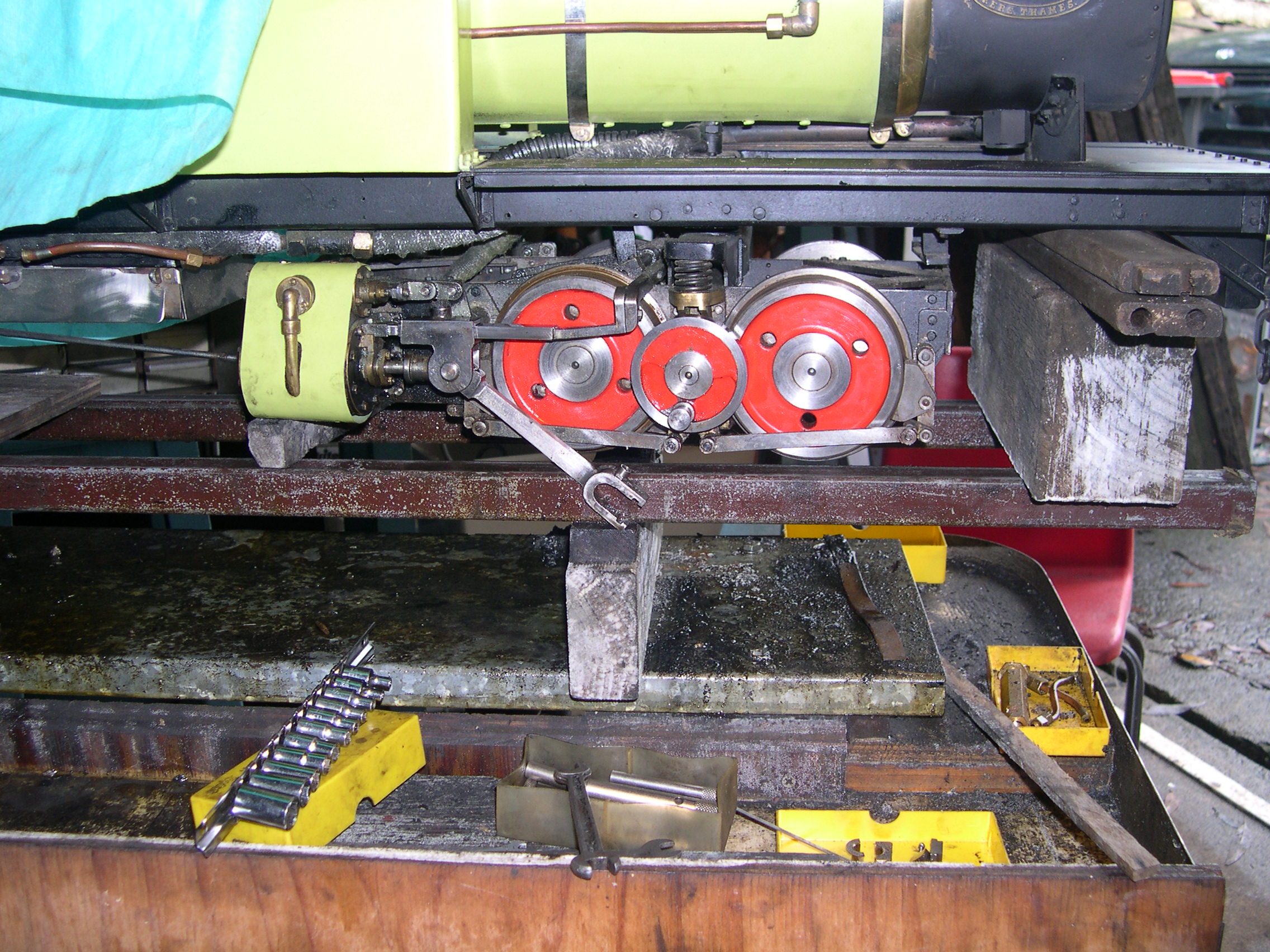
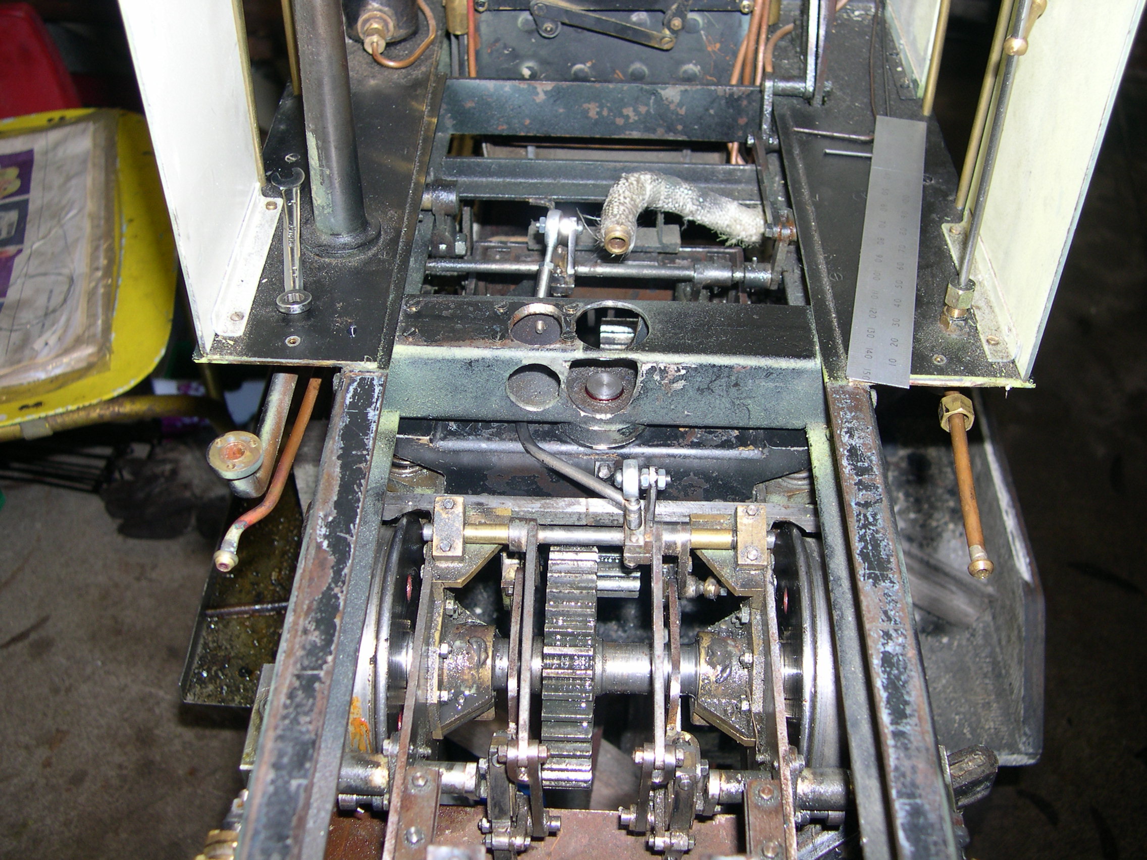
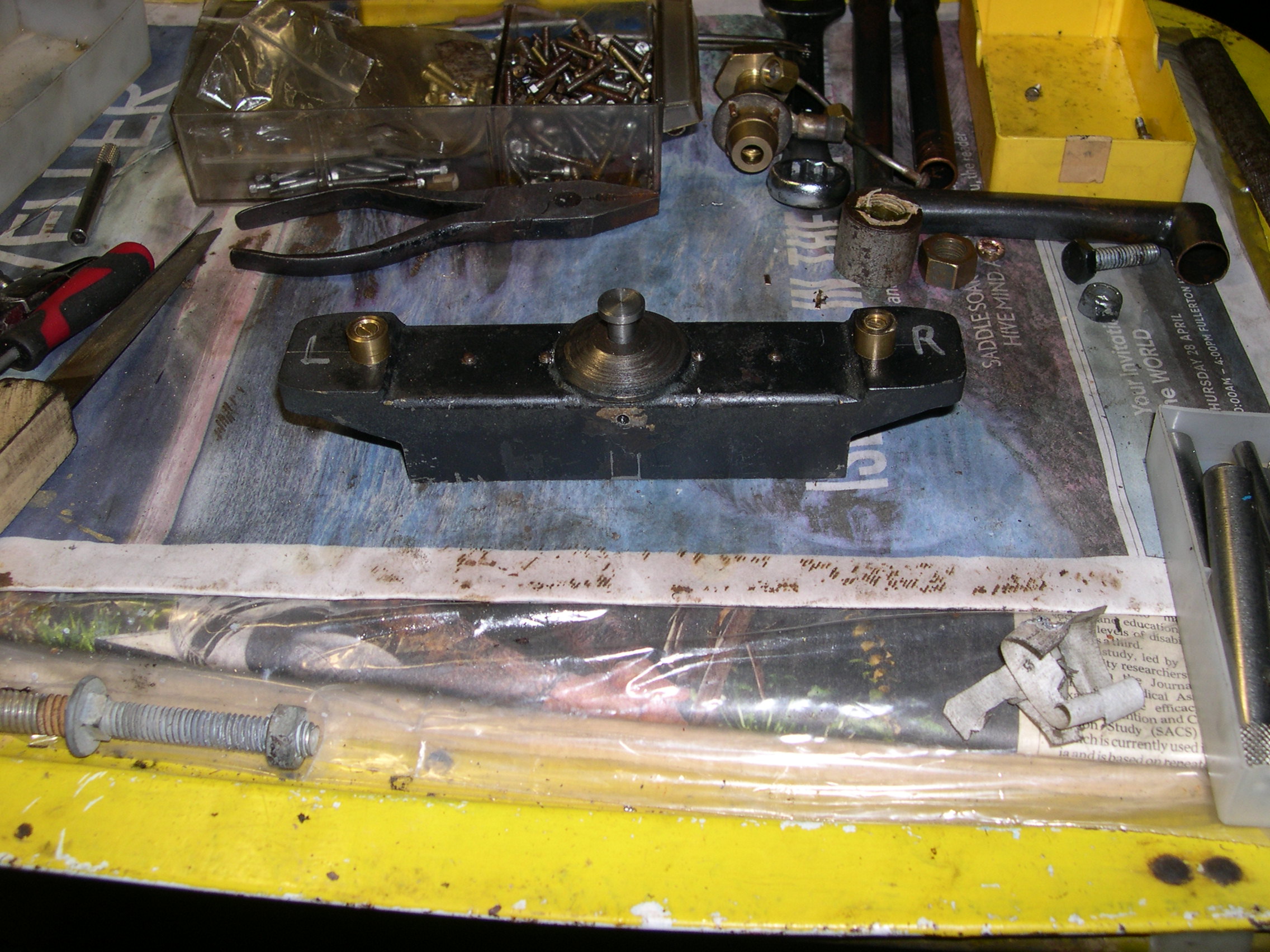
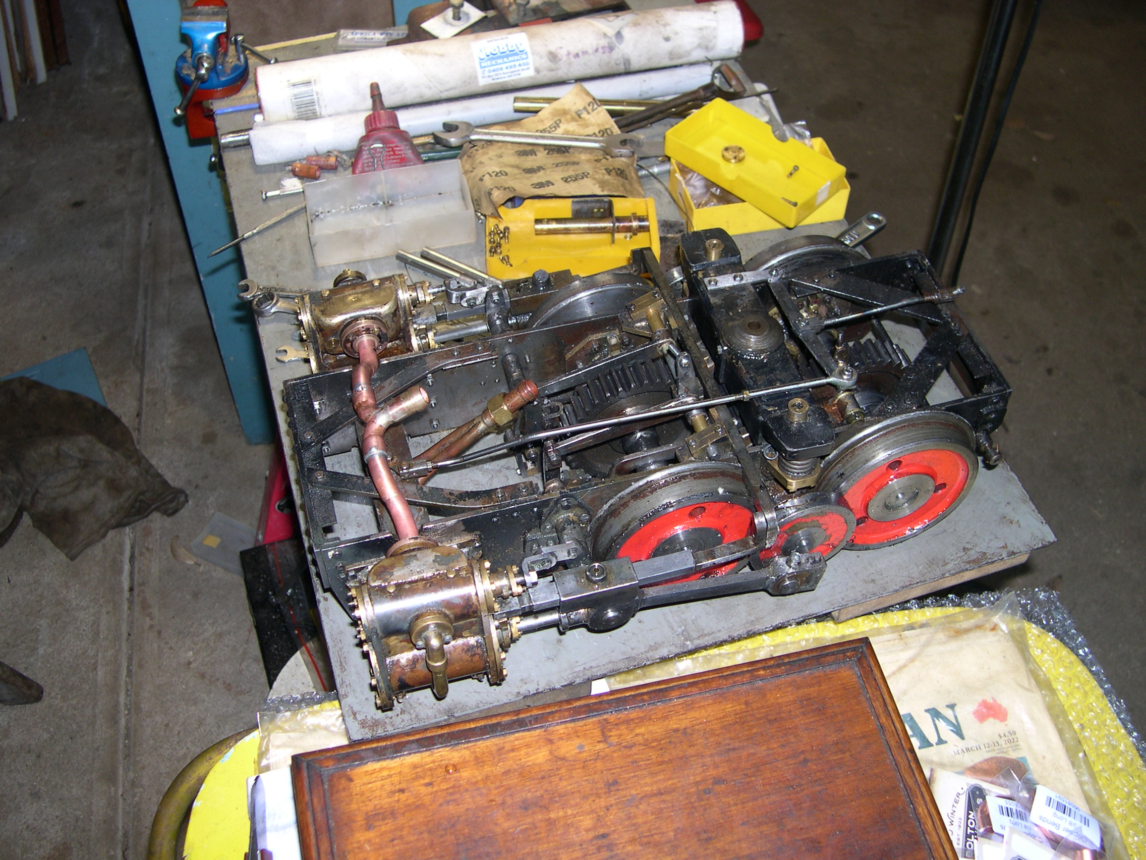
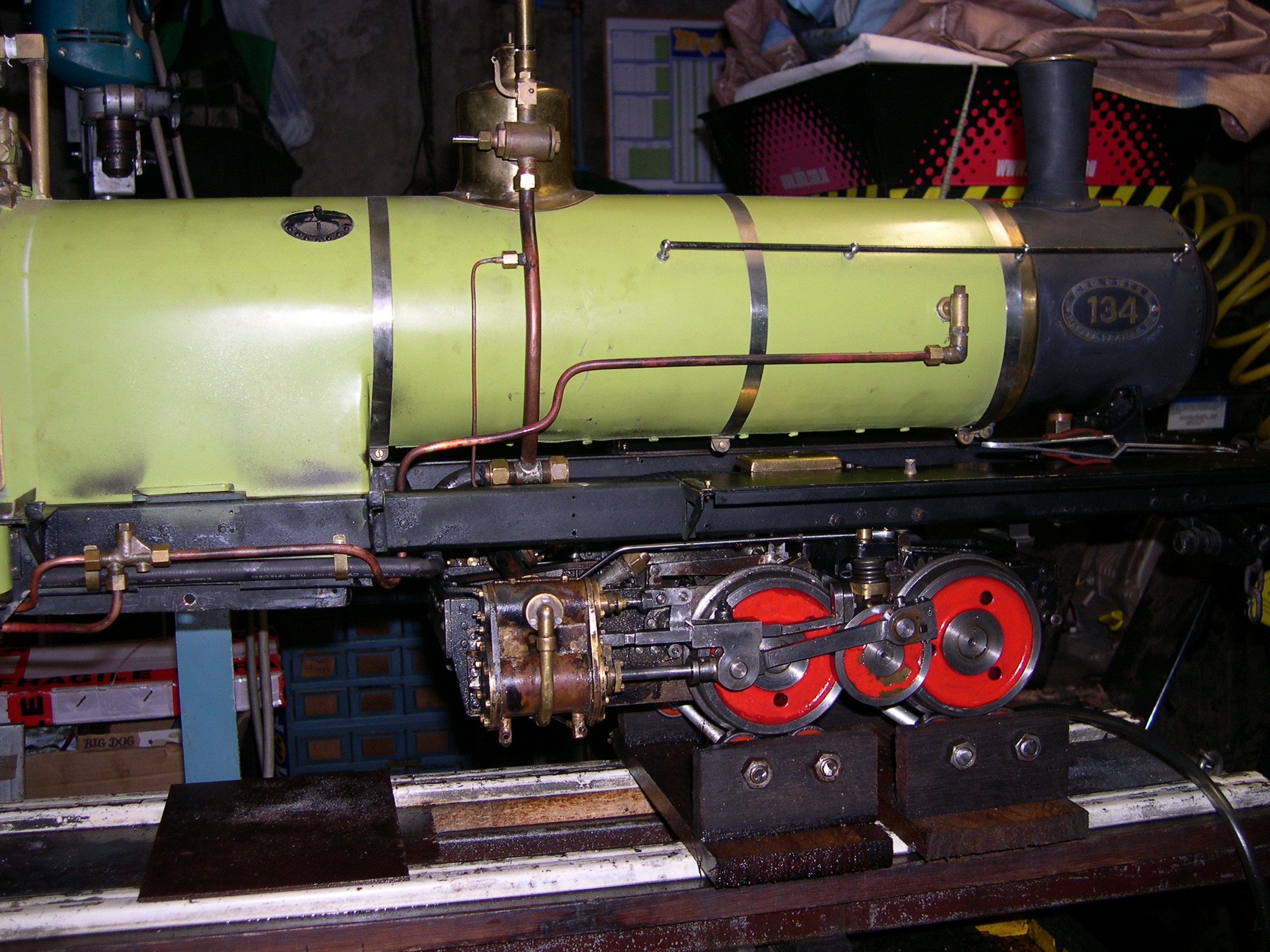
The testing didn't go very well. Both bogies were binding. To check where the problem lay I disconnected the connecting rods. Luckily the big-ends are just like a real loco with split brasses, a wedge, and a keeper. The second photo below shows the assembled big-end and all the amazing detail on the fabricated cylinder and valve caps. The binding appears to be due to the gears which are meshing a little tightly.
The gear ratio from the crankshaft to the axles is 2:1 and the wheels are 90mm diameter. This means the crankshaft must rotate just over seven times for the loco to travel one metre. For a speed of 1km/h the crankshaft needs to rotate twice per second or 118 times per minute. I'd say that 2km/h will be the top speed for this loco. Definitely too slow for running with other locos on a club track. Of course it could be thrashed and run faster but this would look silly and wear it out prematurely.
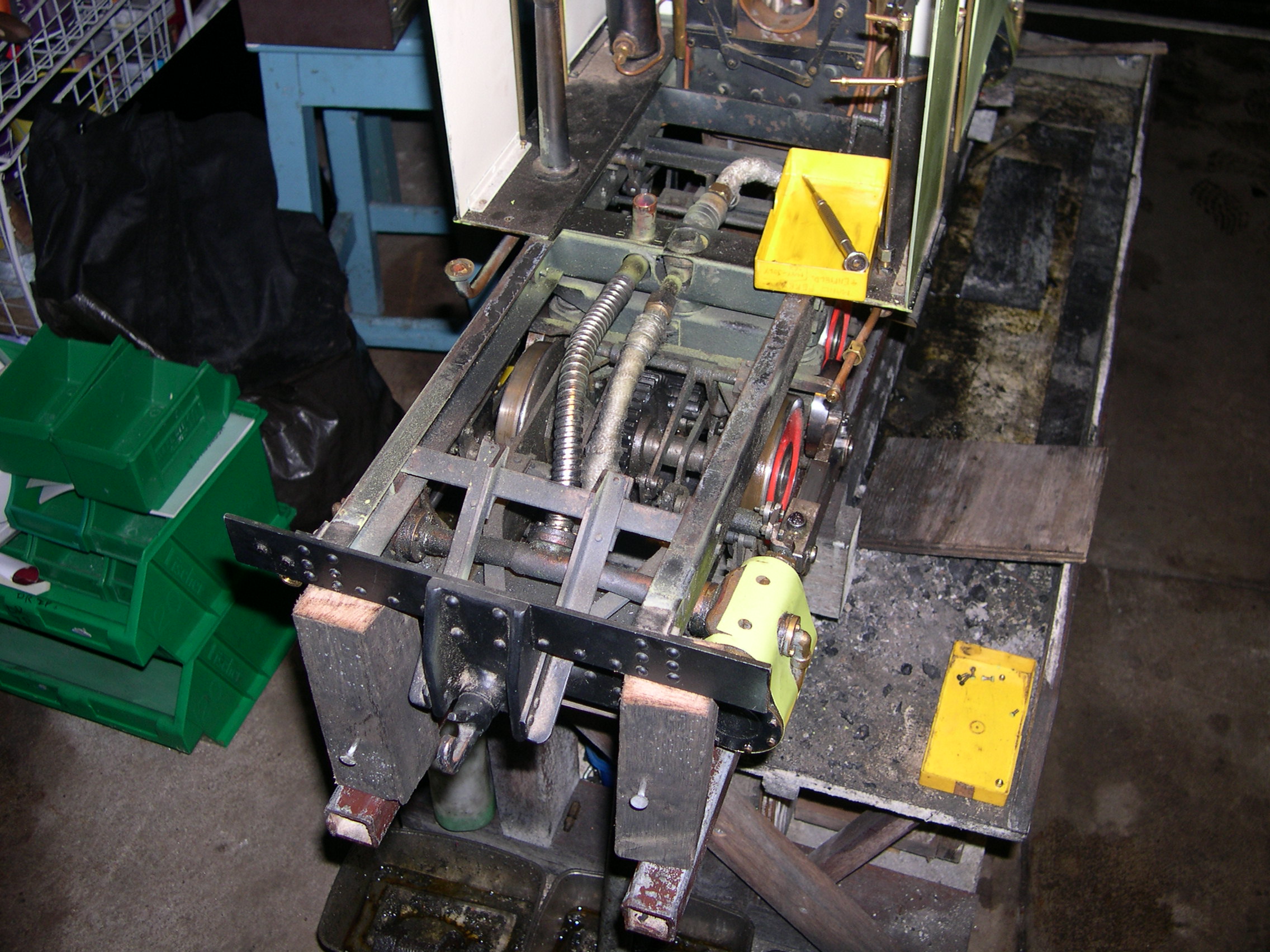
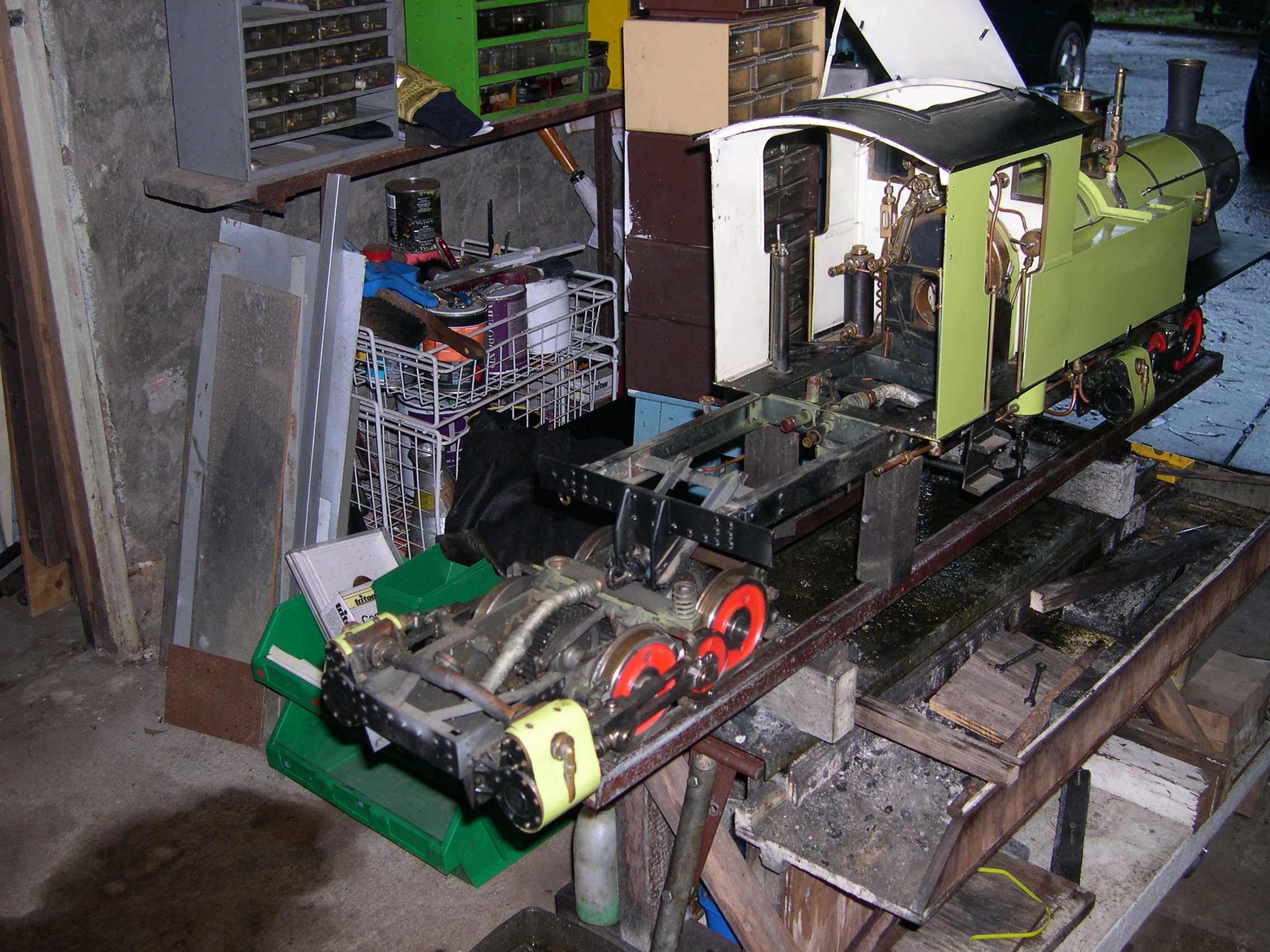
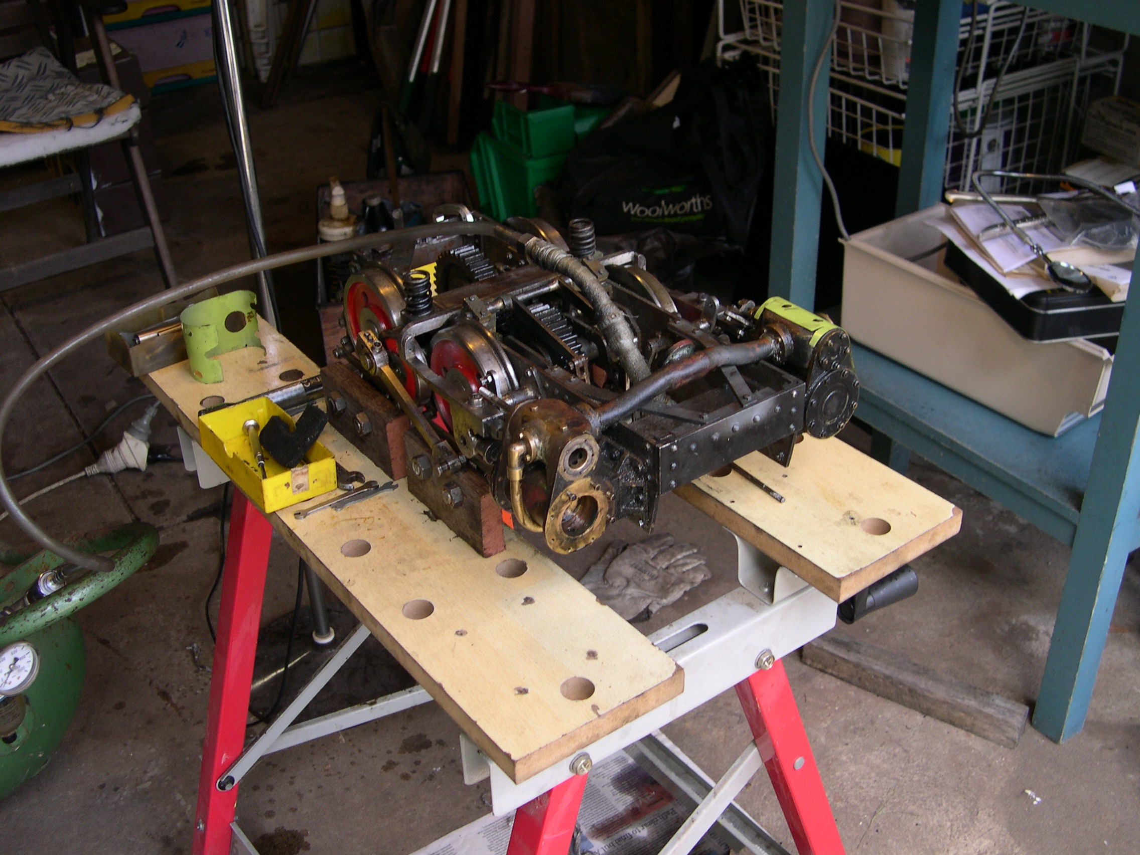
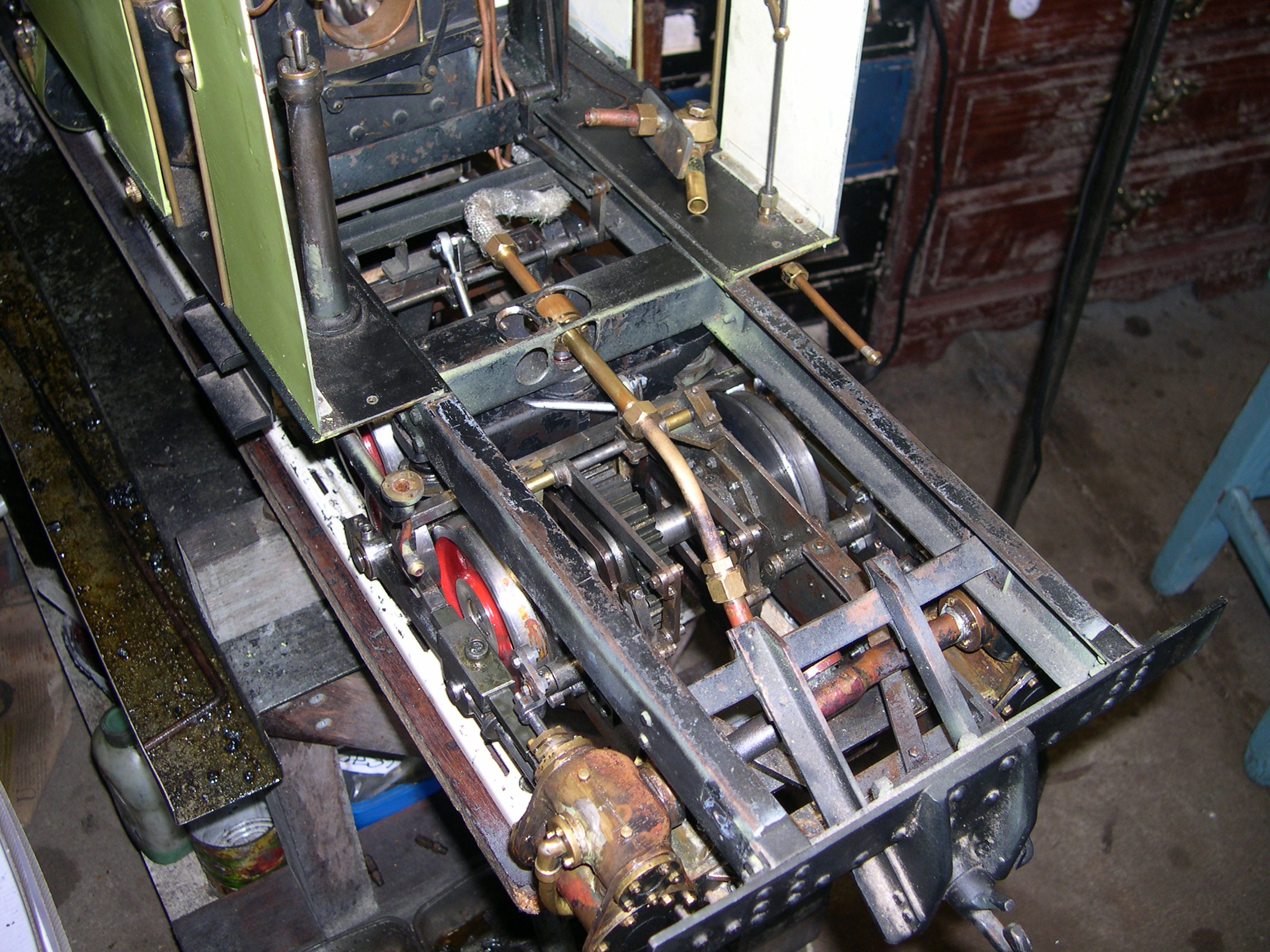
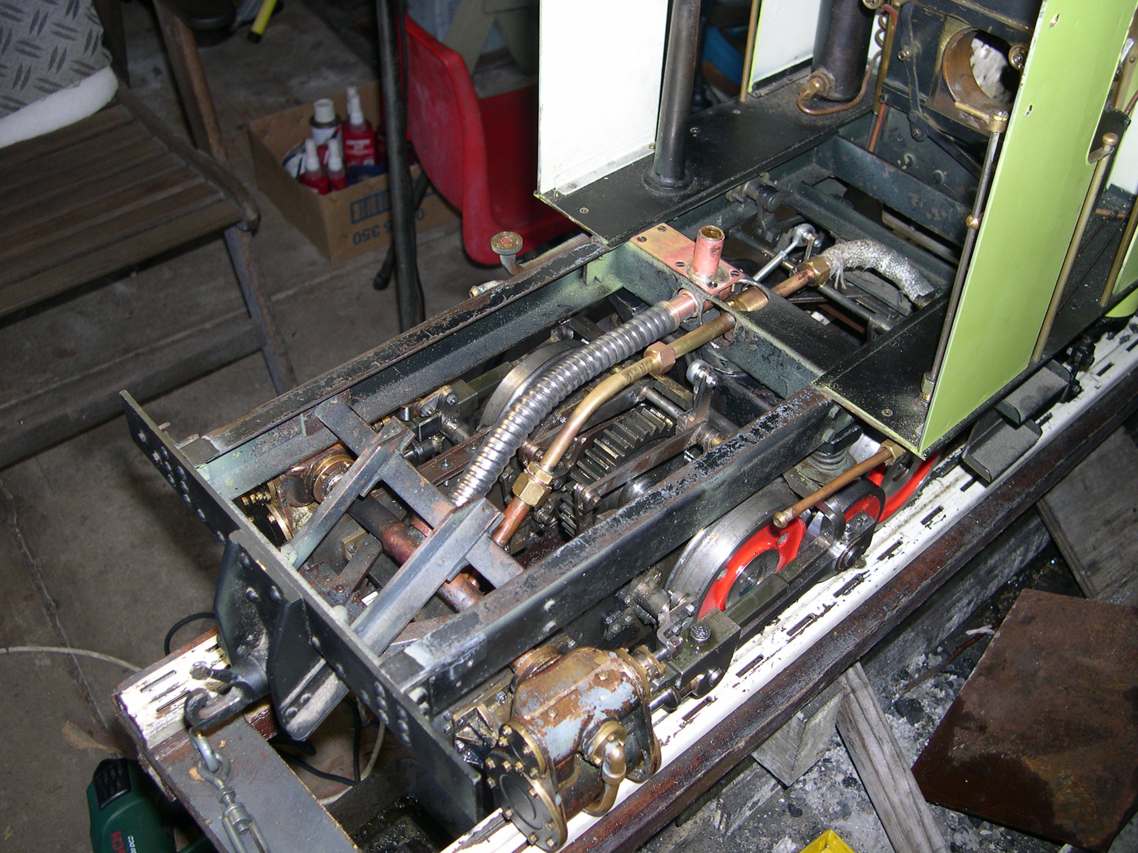
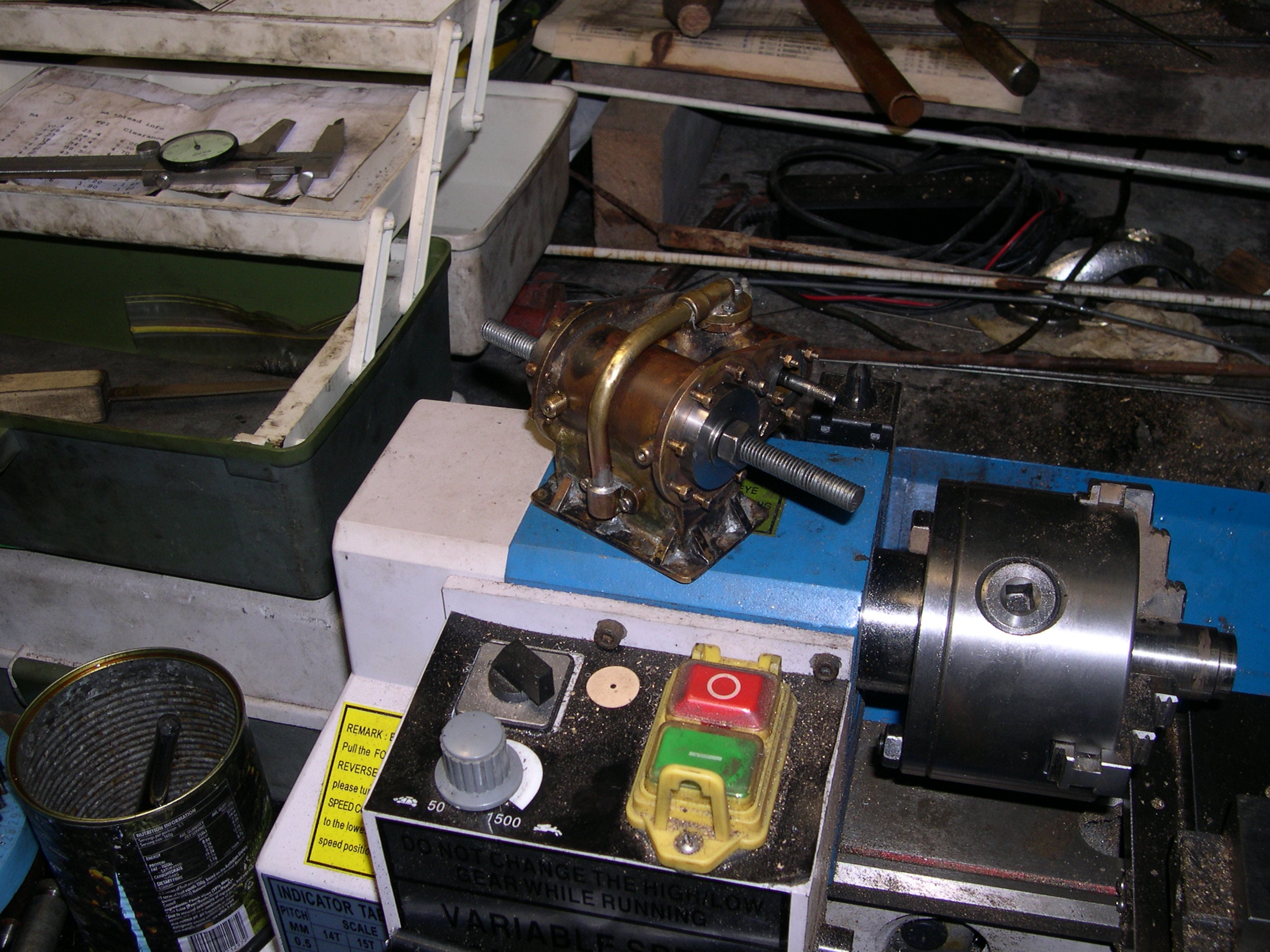
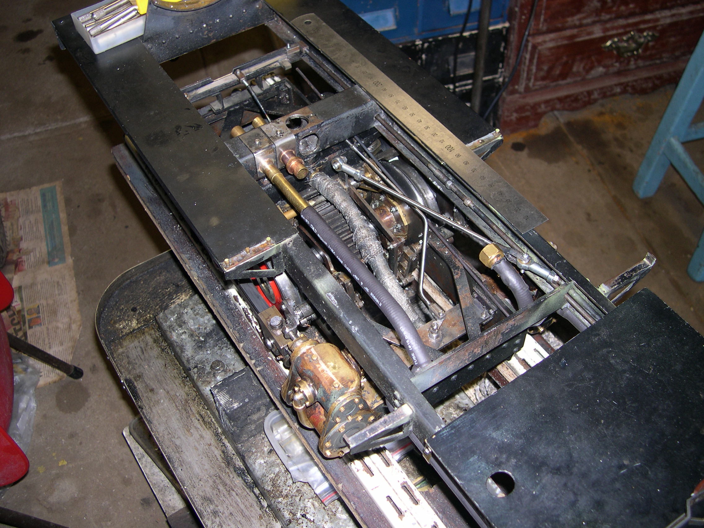
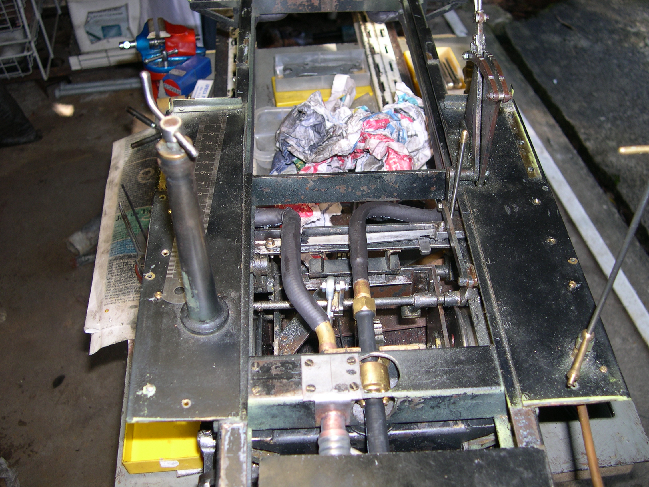
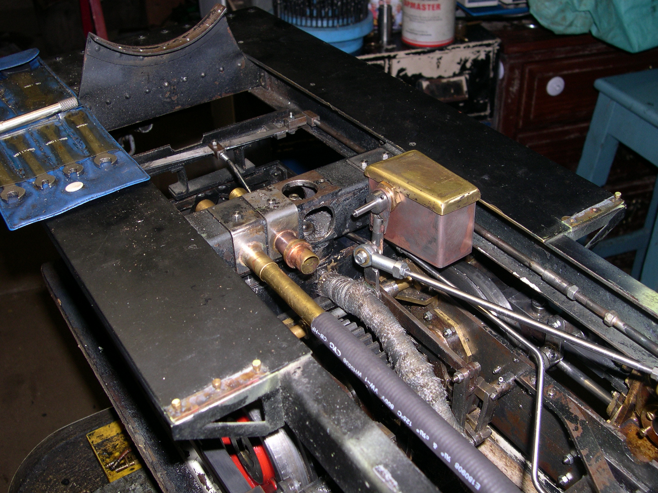
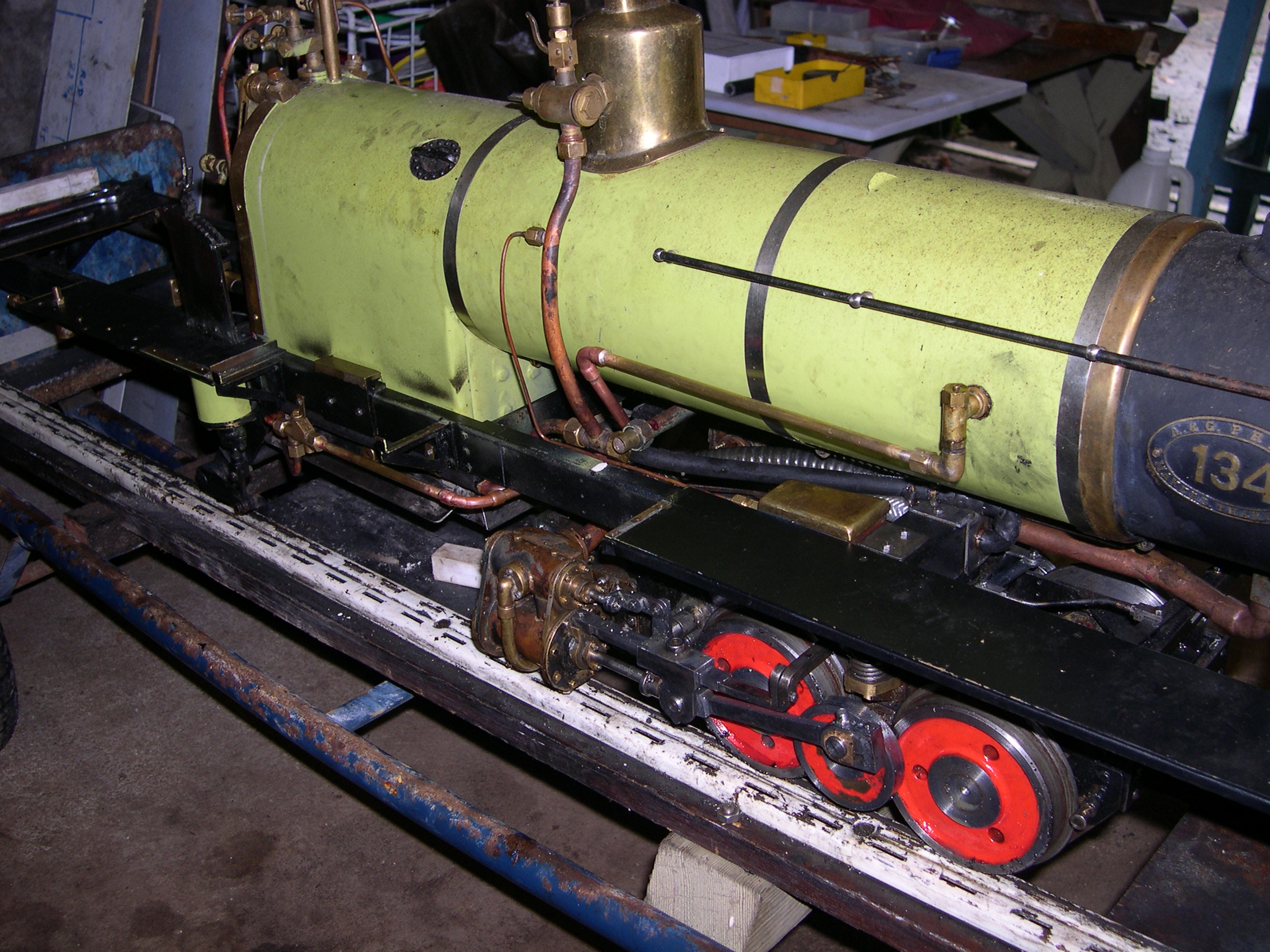
The back bogie stopped working in reverse as one of the eccentrics came loose. Accessing most of the bogie is very difficult even over a pit so I decided they have to be removed for servicing. Removing the bunker provides access to the pipes and reversing control arm for the back bogie and also the strap that holds the sprung bolster in position. It really would be good to have a stretcher bar and jacks to support the loco here so the bogie can be wheeled out. Looks like I'll have to make such an implement.
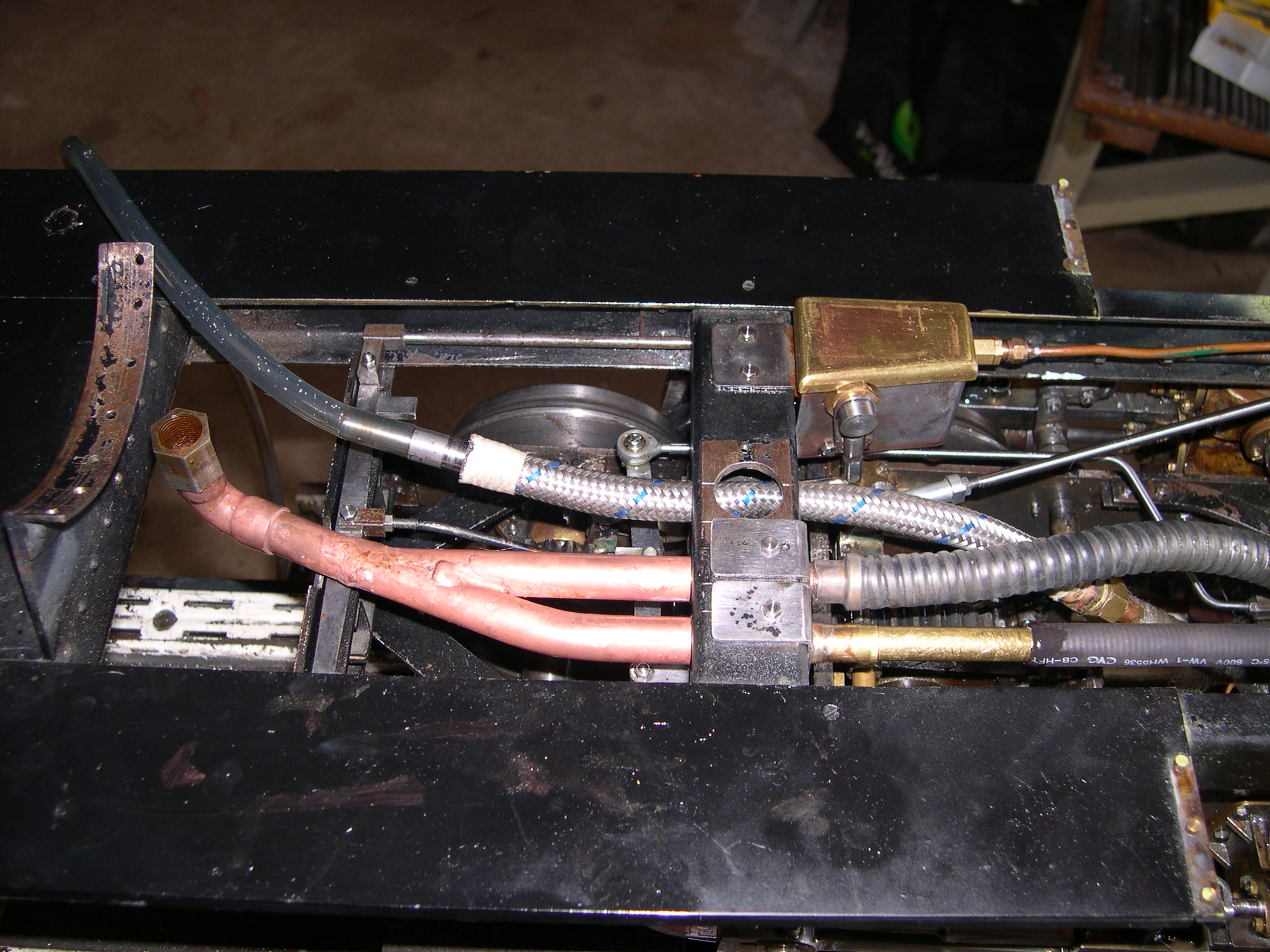
Notice the piping for the bogie. The steam exhaust is a flexible corrugated pipe with a flange mounting at the bogie and a screwed connection at the crossmember. The steam feed pipe is rigid with a ball joint at the crossmember and a sliding connection next on the pipe. Both these connections handle the bogie movement when cornering. What doesn't work is the reversing control rod which is near the right and the expansion link position is affected badly by bogie movement.
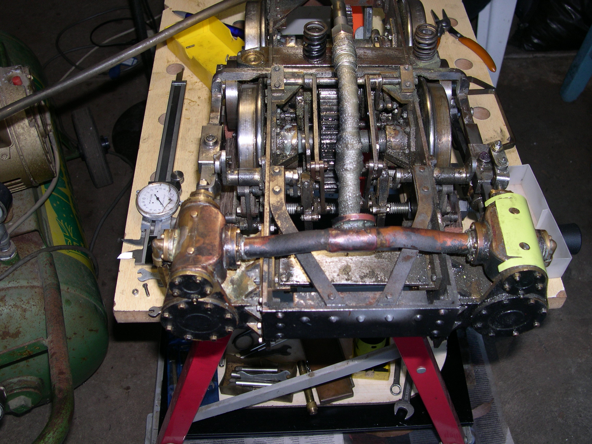
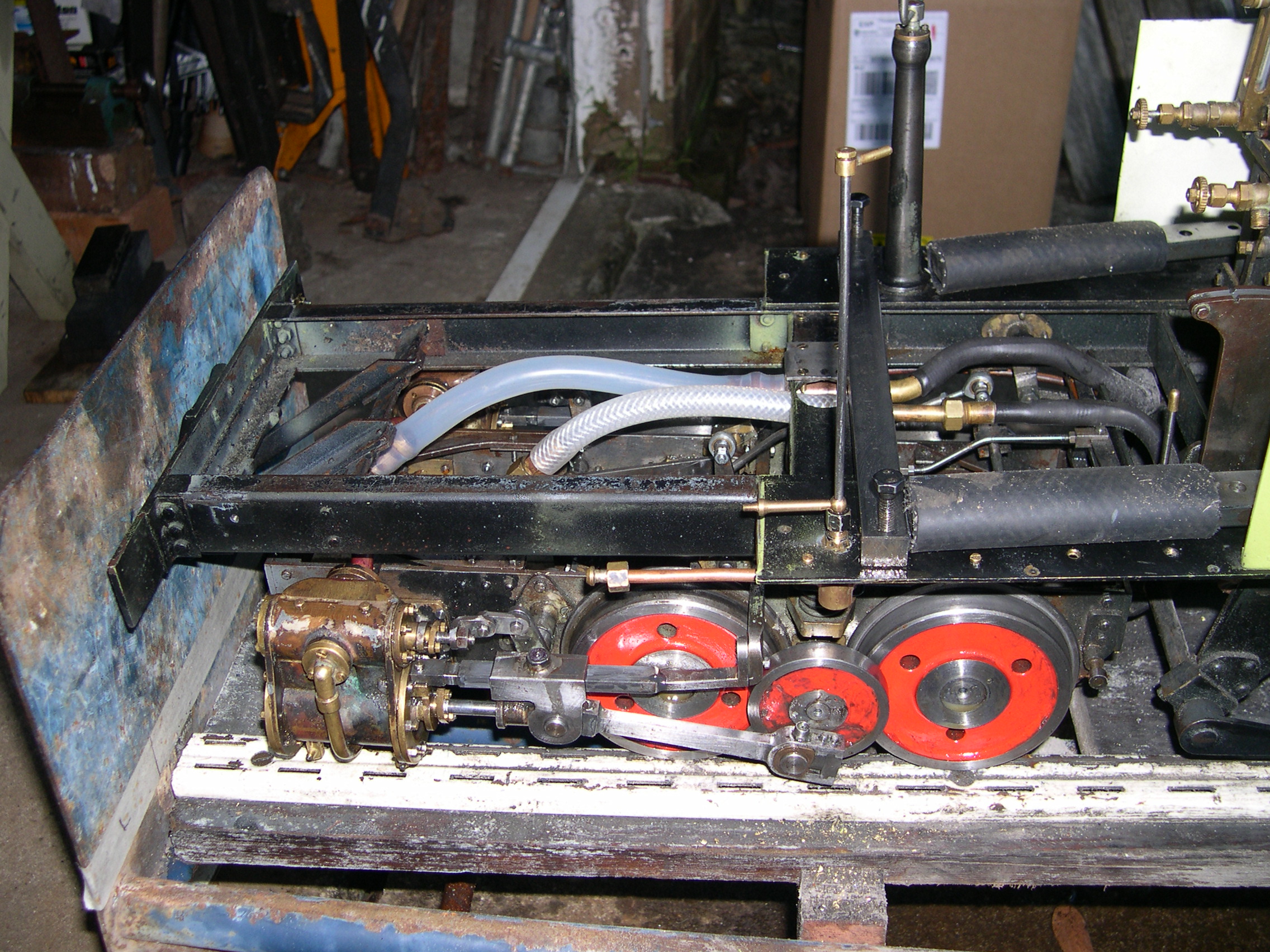
I made some rollers using 6200 sealed bearings. This is important here as the axleboxes only have a bearing surface in the top half and running the loco with the wheelsets suspended is not a good idea. The bottom halves are removable and have an oil pad. The rollers will be used when this loco will be run on a demonstration stand. Such a demonstration is one of the planned goals in this modifications project.
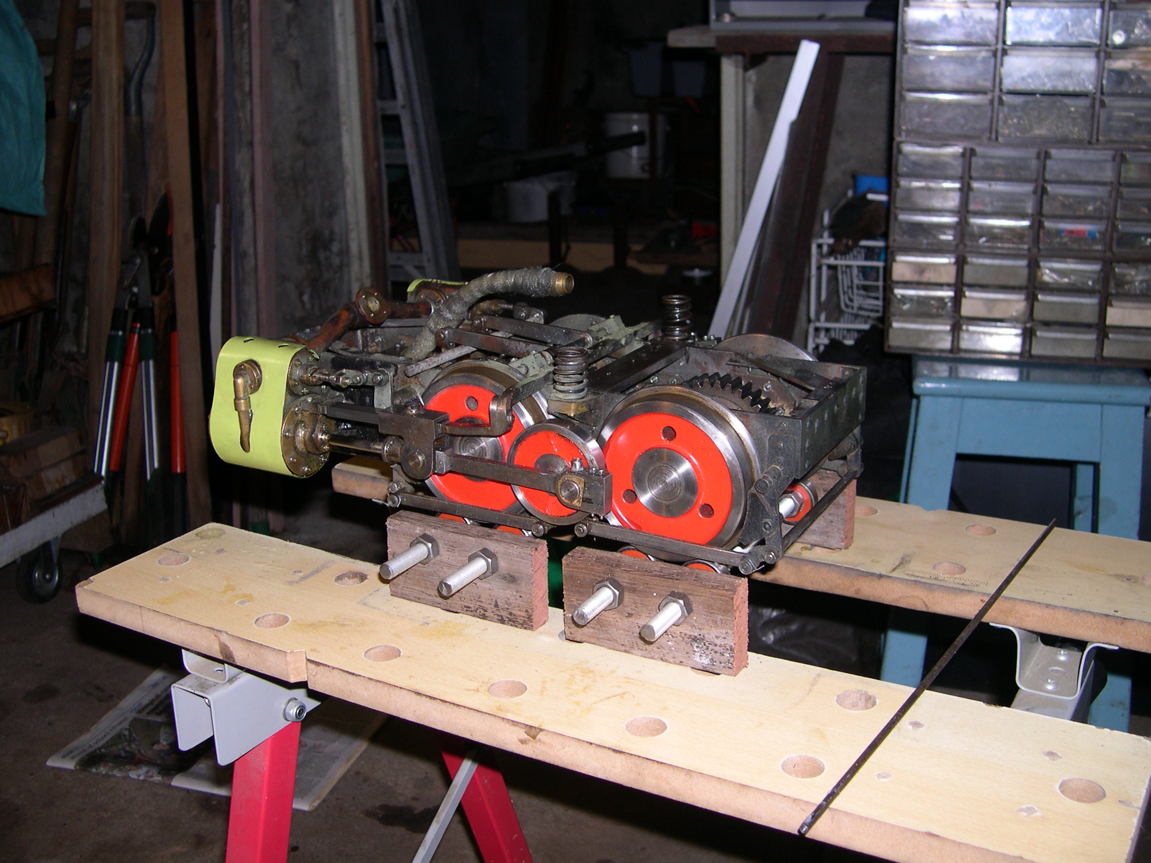
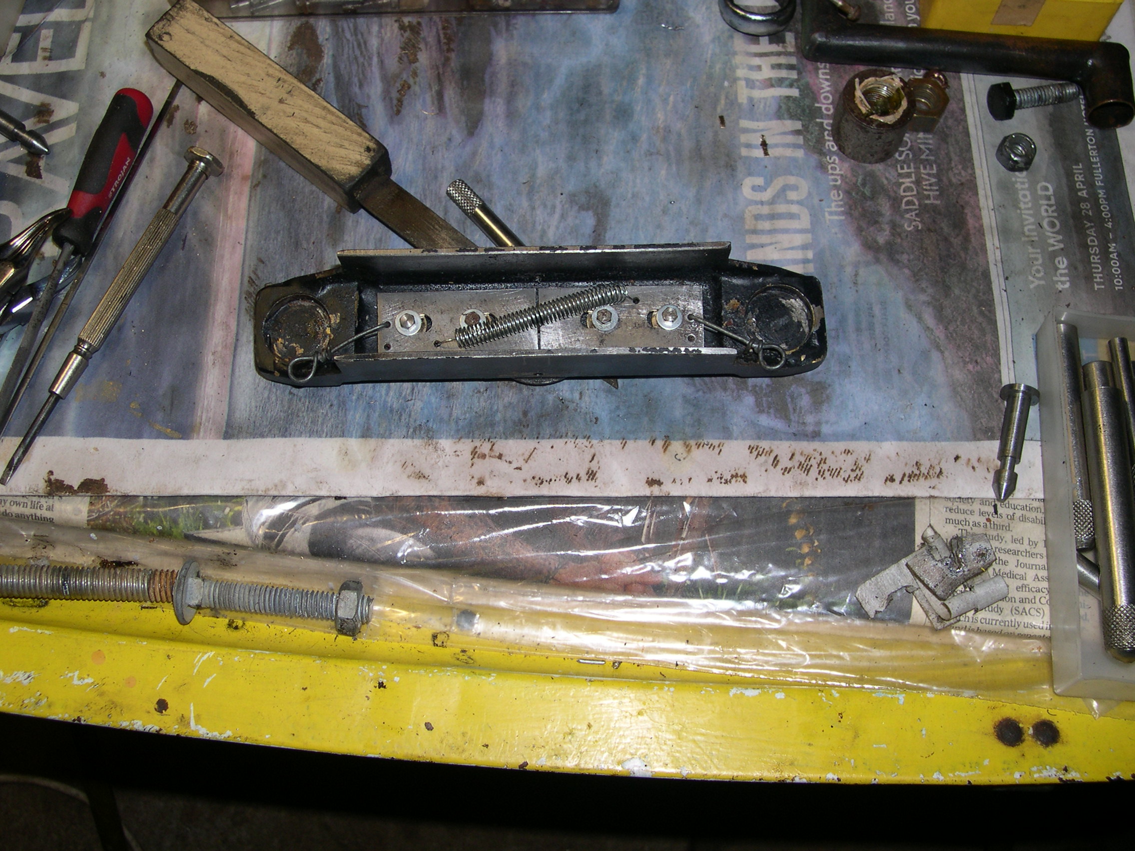
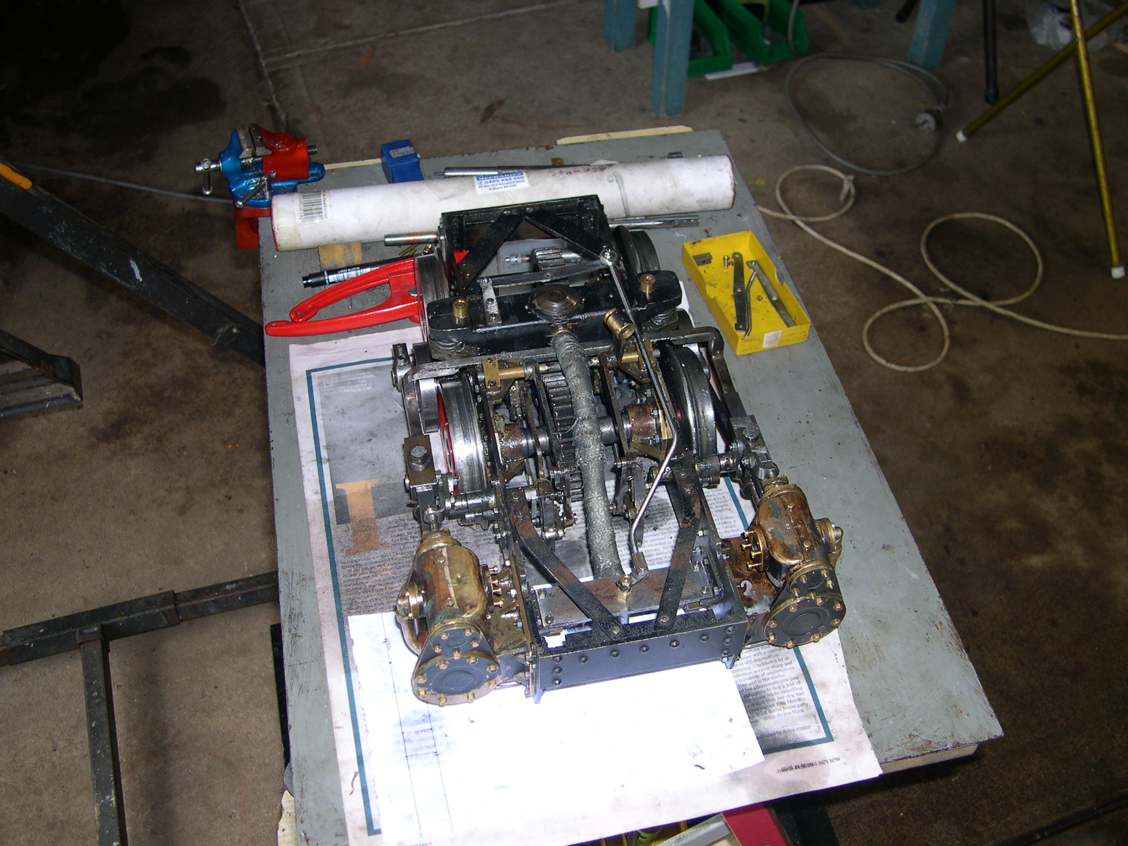
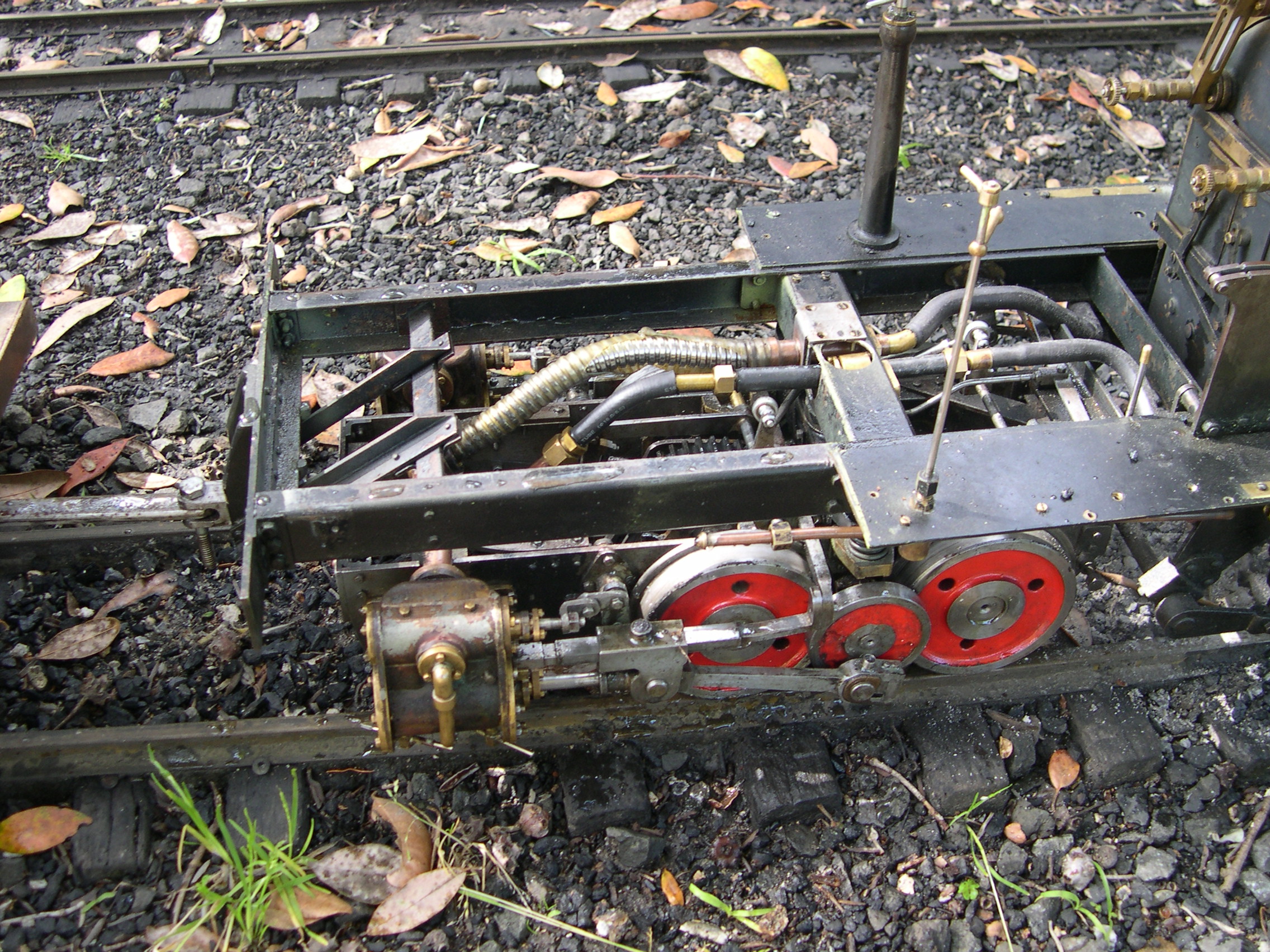
The picture of the inverted bogie shows the Stephensons valve gear and the brake rigging. The drain cocks are little safety valves from coffee percolators. Replacing these with manual cocks is on the cards. The brake rigging is true to life but not compensated nor adjustable. This was recognised as a problem in the real bogies and corrected in the later version of the bogies. The later version had inclined cylinders rather than horizontal possibly to provide more ground clearance.
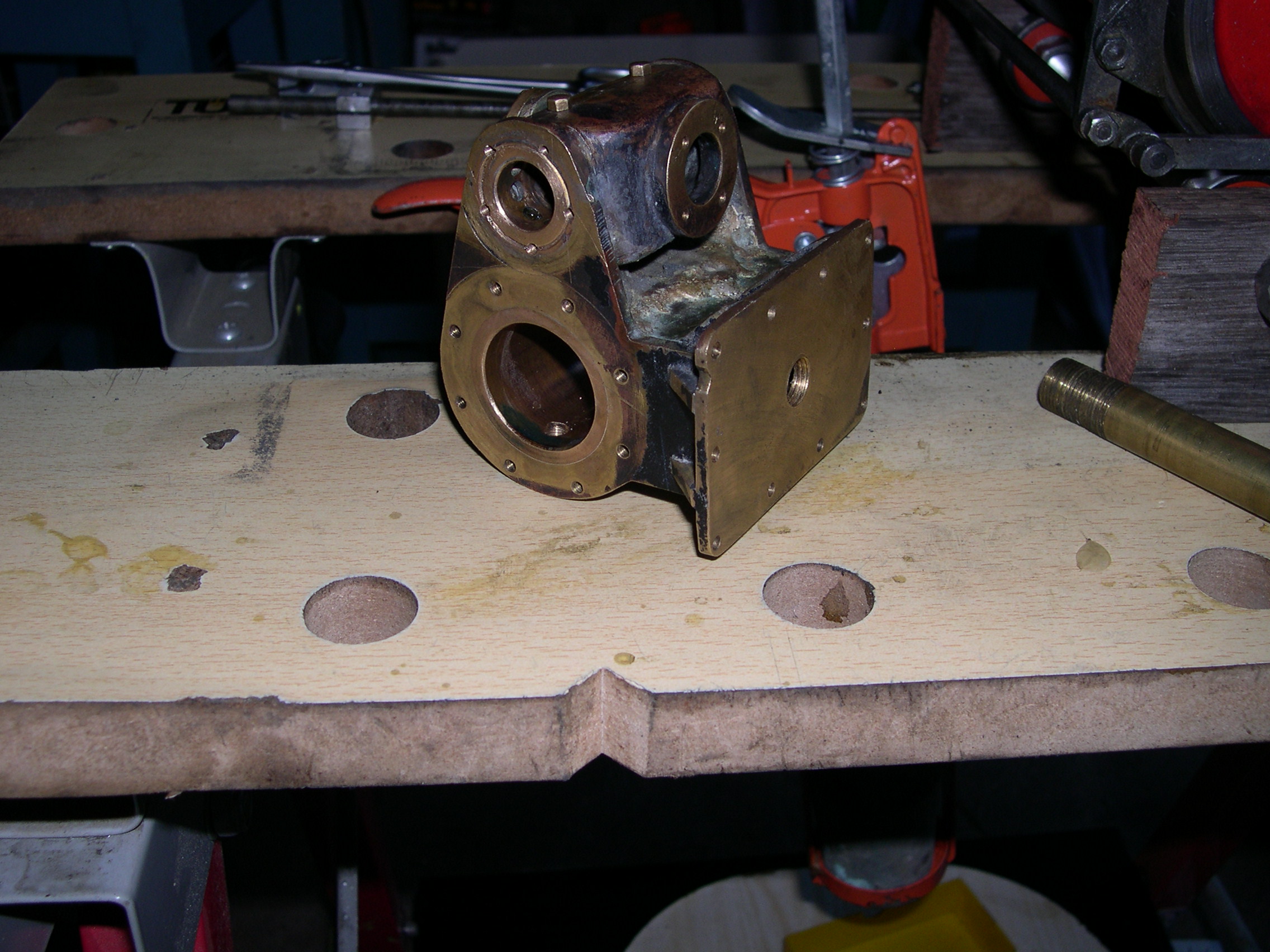
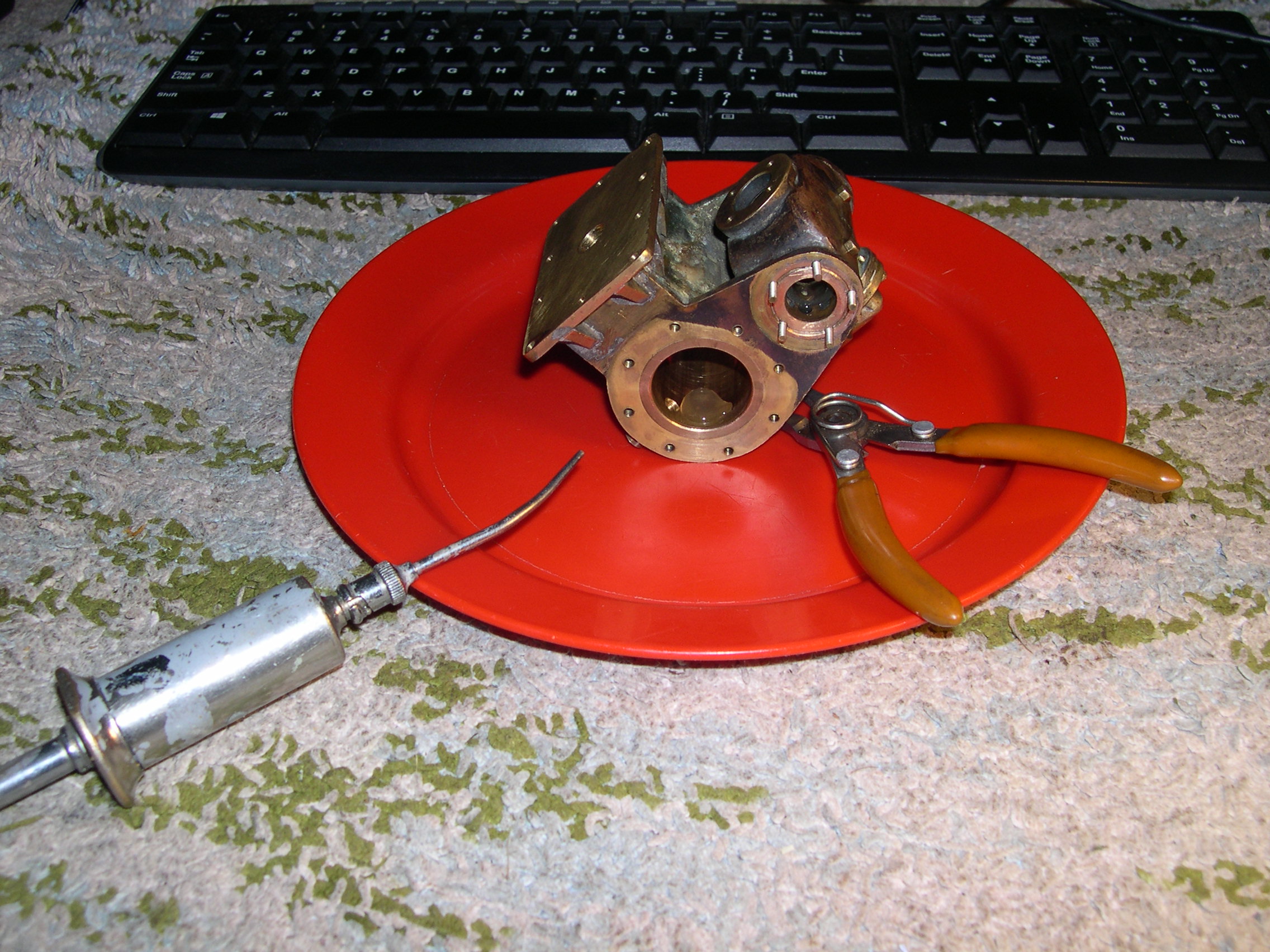
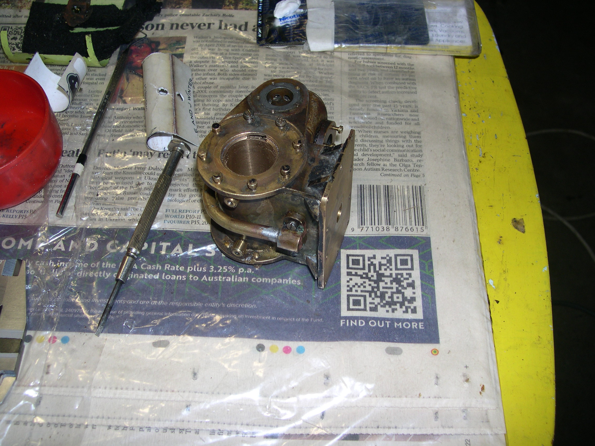
Testing here showed a problem with the left cylinder (remember that the cylinders are at the back of the bogie). There was a serious blow in one quadrant of revolutions of the crankshaft and it was when air went to the back of this cylinder. Removing the covers didn't reveal the leak so the cylinder was removed and disassembled. Rather than being made from a casting these cylinders are fabricated using bronze bushes and brass plates.
Eventually I discovered a leak between the cylinder back port and the exhaust port. This was a brazing pinhole and I could poke a piece of 8A fuse wire through the hole. My fix was to poke a piece of copper wire into this hole and seal it with Loctite 620. Both cylinders still have a slight blow past the valve bobbins. Getting piston valves to seal any better seems very difficult to me.
These fabricated cylinders are a work of art. The steam enters via the mounting plate and travels to the valve via the little pipe on the outside. The exhaust is via the manifold above the mounting plate. The only issue is that there should be a groove from the drain cock hole to the end of the cylinder to allow for drainage when the piston is at the ends of its stroke. A facility to squirt oil into the cylinder at the end of a run would be a nice extra.
After re-assembly I refitted the cylinder and tried to set the valves. For setting the valves I measured when the steam ports just open and averaging these gives me the midpoint. Then I measure the full travel of the valve in full gear and then adjust the linkage so the travel midpoint matches the opening midpoint. Finally I adjust the eccentric sheave position on the crankshaft so the steam ports open just after the ends of the piston stroke.
The bogie is running better than before but still binding slightly on the gears. The next step is to remove the wheelsets and make sure it will run smoothly with just the crankshaft. Also, access to the eccentrics will be much better so this is definitely the time to make sure the valve settings are optimal.
I removed the wheelsets to do an air test with just the crankshaft. Unfortunately the rotations still weren't smooth and it became apparent there was a blow from the front of the left-hand cylinder to the exhaust port. This was much less than the previous leak. To verify the leak I plugged the cylinder port in the valve liner and put acetone in the exhaust port. Sure enough some slowly leaked through to the cylinder. As before I poured Loctite 620 in the port at the valve liner and spread it around to hopefully find and block the leak.
While the cylinder was here I machined little channels from the drain cock holes to the end of the bore. This ensures there is a leak path when the piston is at the end of its stroke and covering the drain cock hole. I wonder why people don't put the holes in the end caps rather than the bore. This would avoid the risk of packing or rings catching on the hole and it would be impossible for the piston to block the hole.
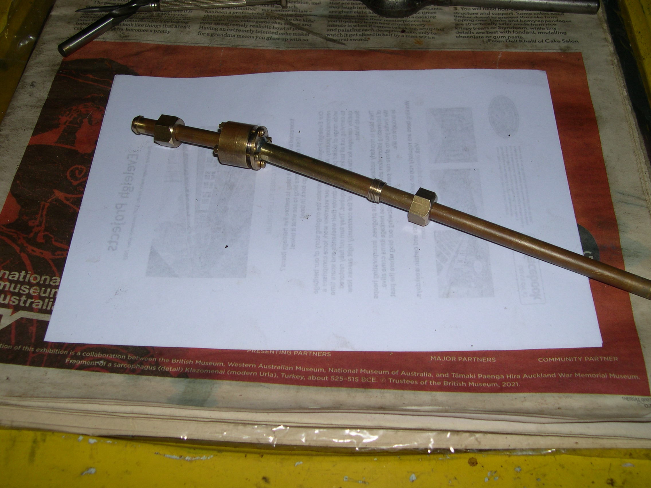
The old flexible joint for steam to the back bogie was a swivelling joint (only) that didn't allow for bogie movement due to grade changes. The real loco had two ball joints with a sliding joint in between. The replacement joint near the bogie pivot is a ball joint using a 1/2" SS ball and a Viton O-ring to hopefully seal it.
Here is the steam pipe joint assembly and a picture of the trial fit after the last pipe was bent and trimmed to fit. The original Y-connection to both cylinders is hidden behind the frame members between the cylinders. The ball joint is directly over the bogie king pin and the bent pipe slides in the straight pipe from the ball joint.
The issues with this arrangement are that the geometry isn't quite correct and that the sliding joint doesn't slide easily due to the sealing O-ring. A proper arrangement would have two ball joints with a straight sliding joint in between.
So for the front bogie I'm trying reinforced silicone tube. The black tube in this picture is silicone fuel tube from a car performance parts retailer. Subsequently I tested a clear silicone reinforced tube from Gecko Optical in Perth. It is more flexible and initial testing shows no problems. The steam here isn't superheated and normally the pressure won't exceed 40psi because the wheels will spin before this pressure. For testing I've had the loco in mid-gear with the regulator wide open to get full boiler pressure (100psi) in the tube. It hasn't swelled or come off the fittings so it looks like a better solution here.
The initial track test showed the clear reinforced silicone tube used for the steam supply to the front bogie worked well. However, the heatshrink tube used for the back bogie exhaust burst which was unfortunate. Testing showed that even the double thickness heatshrink tube can't handle the exhaust pressure. I did some severe testing with 10mm plain silicone tube and it didn't bulge or show any problems. The severe testing was to connect the steam supply to the exhaust using this tube and then having the regulator wide open with the boiler at 100psi. So the plan now is to use the 6mm ID reinforced tube for the steam supply line and 10mm ID plain tube for the exhaust.
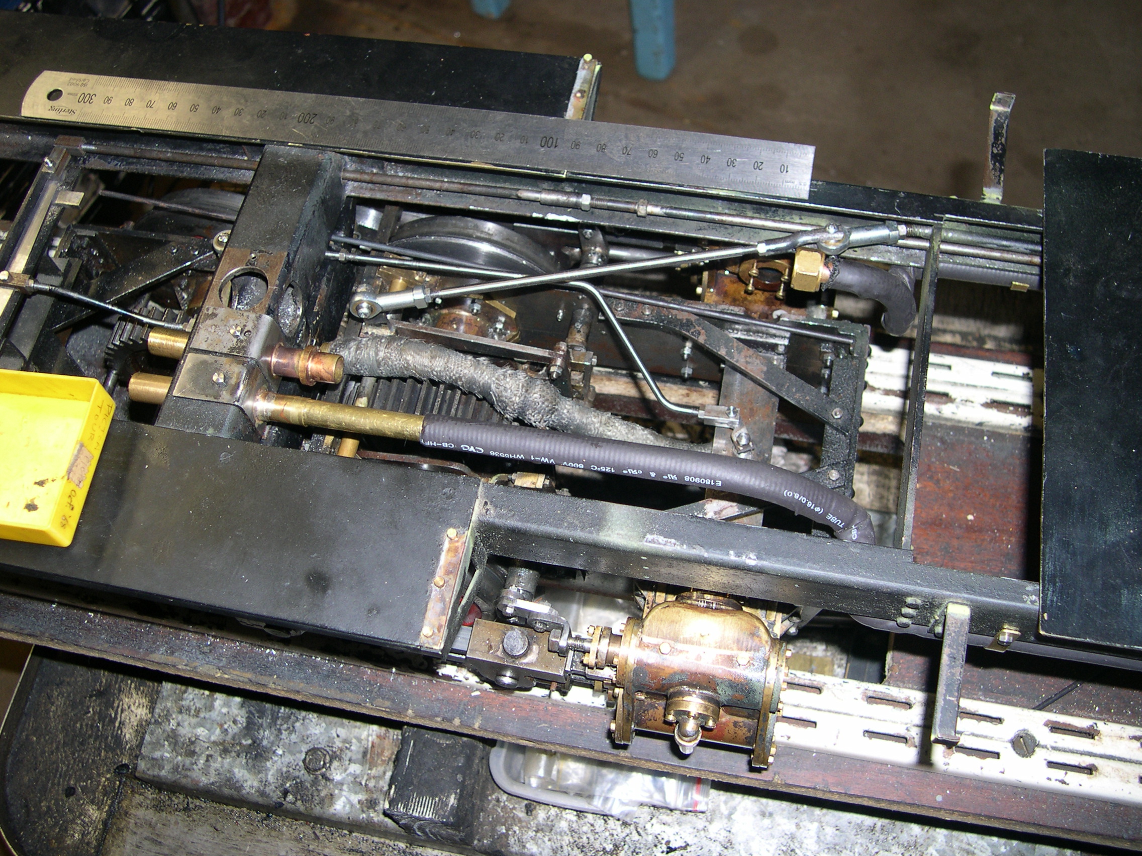
Here is the back bogie after the cylinders have been re-sleeved and proper drain cocks fitted. The steam and exhaust tubes are visible. All the silicone tube here has been obtained from Gecko Optical in Perth. The exhaust tube is the clear tube and just to the right is the reinforced tube for the steam supply. The shiny steel bar across the cab floor is the support bar for the removable footpegs.
The reverser control link to the back bogie was about 50mm off centre meaning it was severely affected by bogie rotation when on a track curve. The replacement linkage has cranks pointing up rather than down and a carefully bent rod with M3 Heim (ball) joints at the cranks. The Heim joint pivot points are diametrically opposed around the bogie king pin to reduce the error movement due to bogie rotation to a minimum.
The flexible pipe for the steam exhaust is metal spiral sheathing for electrical cable (I suspect). It bends easily but leaks like a sieve so not really suitable here. Now I've encased this in clear heat shrink tube and the new front fitting is secured to the front of the crossmember. The fitting on top of the crossmember pushes into the new fitting and is held in place by the six screws. This picture shows the steam supply with the ball joint in the crossmember and the sliding connection after. Also, just visible is the new reverser link with the bent rod that sneaks through between the crossmember and the bolster. Lagging for the steam pipes will come later.
The connections (steam, exhaust, reverser) for the back bogie are now all accessible for disconnection by removing the cab floor.
The heatshrink tube didn't work so this flexible pipe has now been replaced by clear silicone tube. This is amazing stuff because it's so flexible and yet isn't affected by the heat and pressure of the exhaust steam. Of course we'll have to see how long it lasts. The clear tube is the 10mm plain tube for the exhaust. Just in front is the 6mm reinforced tube for the steam supply.
As before it is possible to remove the connections for this bogie (steam, exhaust, reverser, drain cocks) by removing the cab floor. This is critical for maintenance. The front bogie is also removable but not quite as easily due to the extra link for the lubricator and the limited access under the boiler.
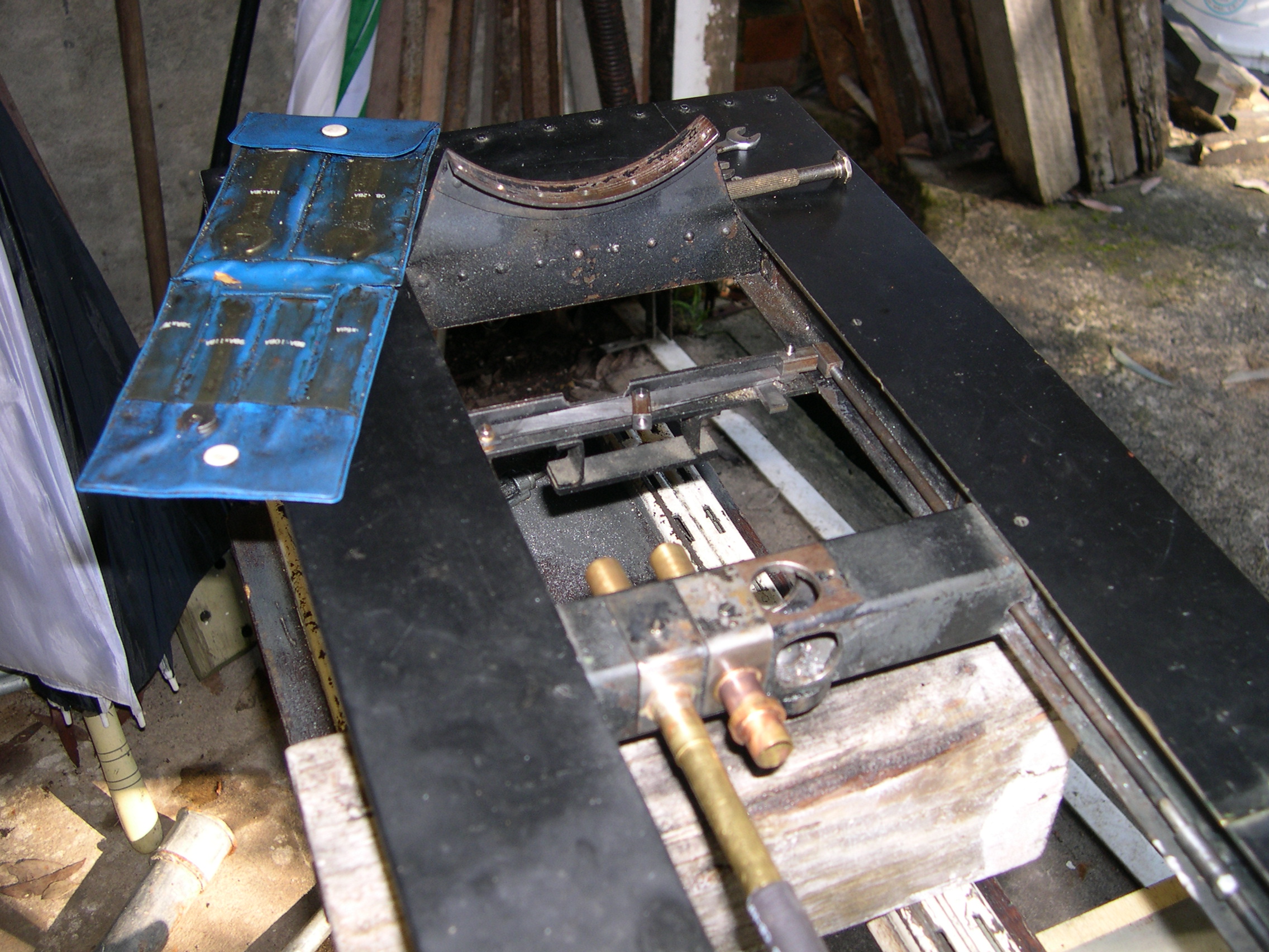
Removing the bogies for maintenance required serious disassembly to access the pivot bolt that connects the bolster to the crossmember. So I've made new king pins that are permanently fixed to the crossmembers and have a groove for the new quick release plates that live in the bolsters. The bolsters are above the springs and now have spacers to stop tilt which will strain the kingpin. The spacers will limit the tilt to 0.5mm. Pulling both little loops near the spring recesses will release the bogie.
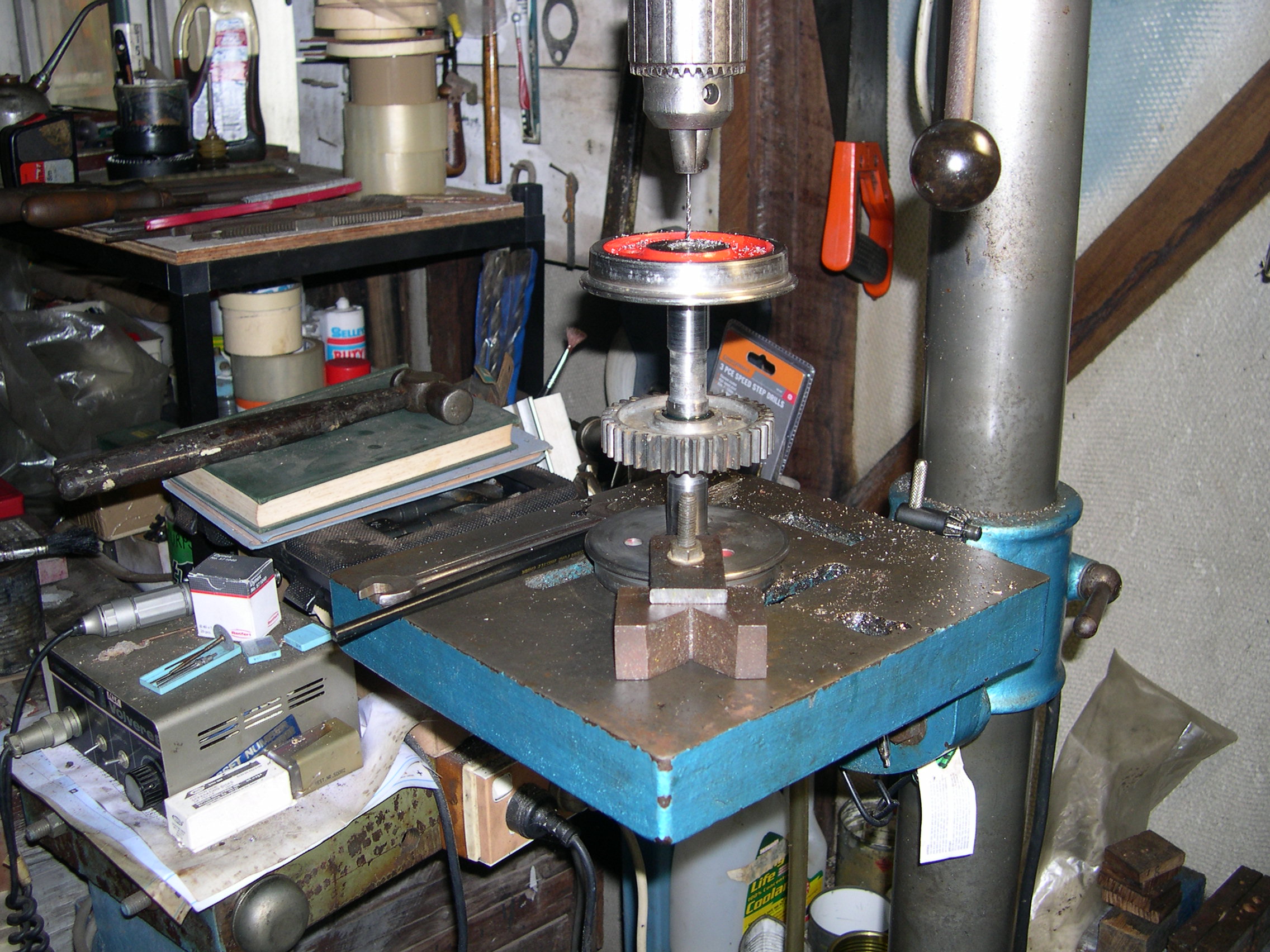
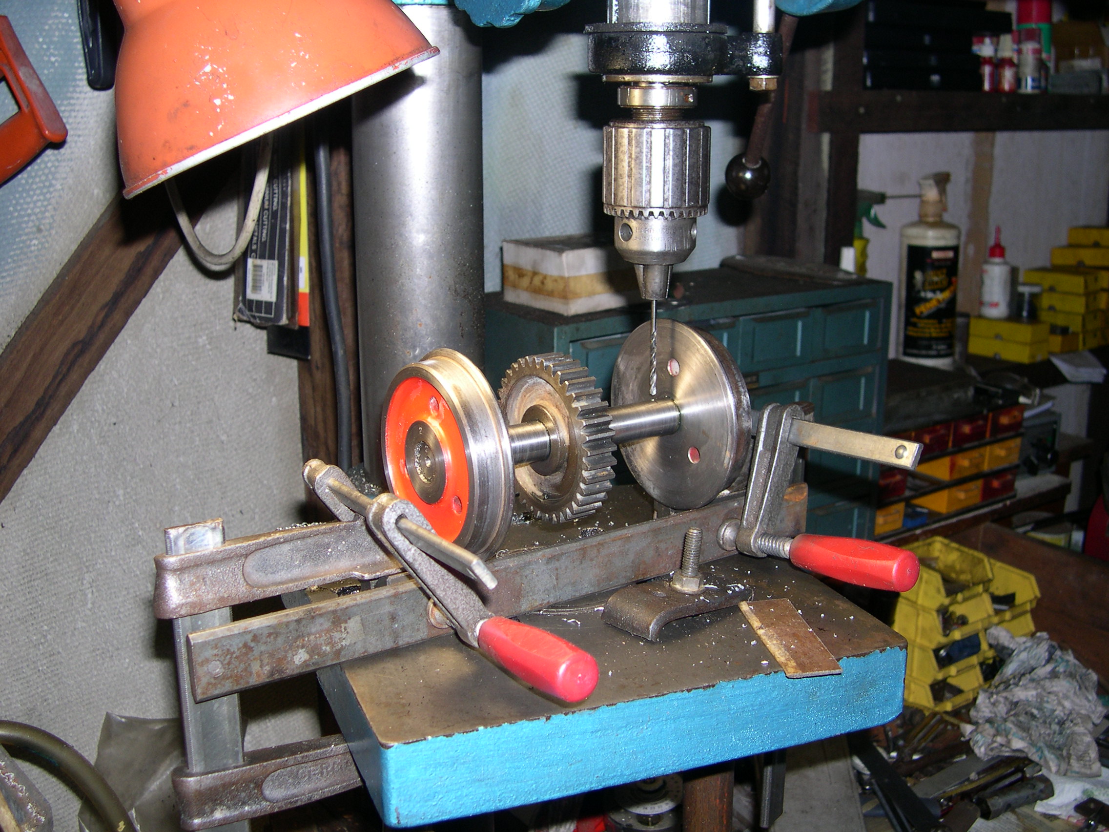
Oiling the locomotive is difficult. To facilitate oiling the crankshafts and axles we now have holes in the axle ends and cross holes to a groove in the axles/shafts. The end holes are 2mm dia and 30mm deep and drilled carefully so the cross holes meet them. Luckily all holes so far have worked. If a cross hole didn't meet the deep hole I guess I'd just have to make a second cross hole. I still haven't found an easy way to oil the eccentrics and expansion links.
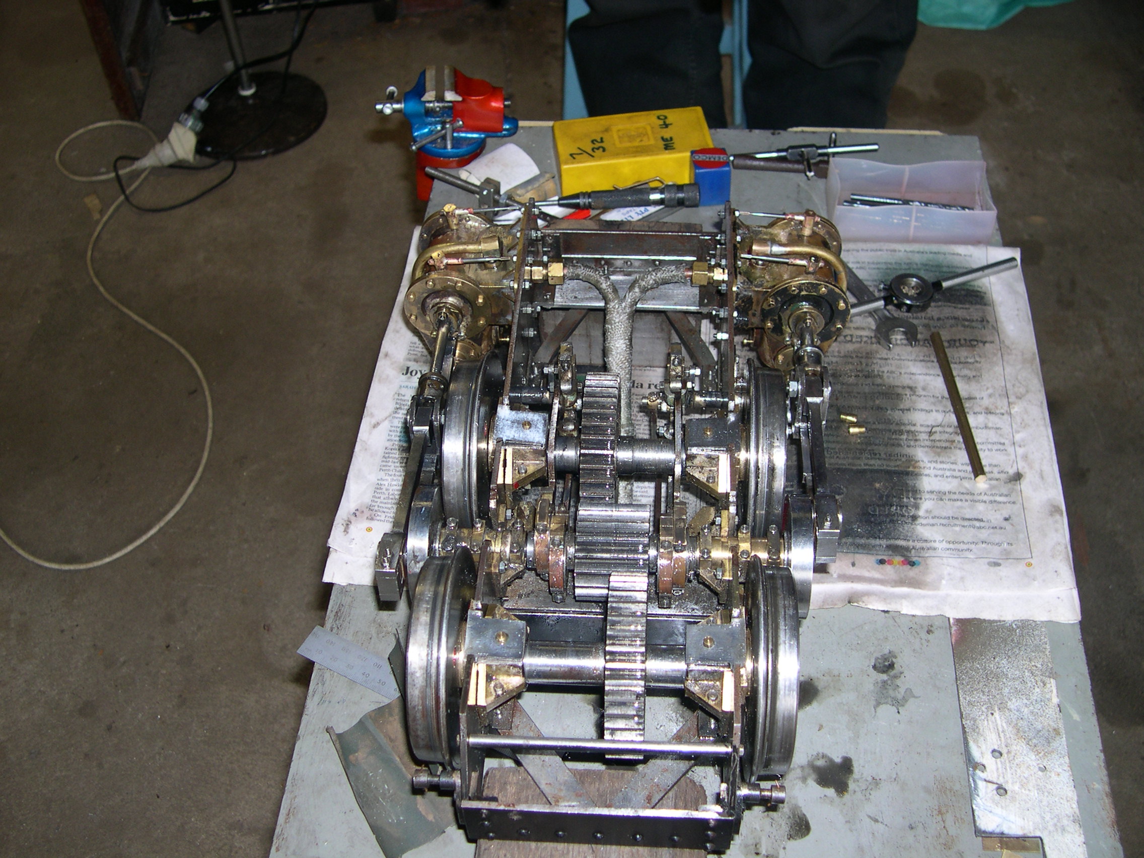
Notice that the wheels have been pulled off the axles slightly. This is because the loco is being regauged to run on my 134mm gauge track. The wheels end up being very close to the crank wheels and require new thrust washers to keep the wheelsets centred. Normally I wouldn't change a standard 5" gauge loco but in this case the loco will be too slow for club tracks and much more suitable for the Banool 134mm track.
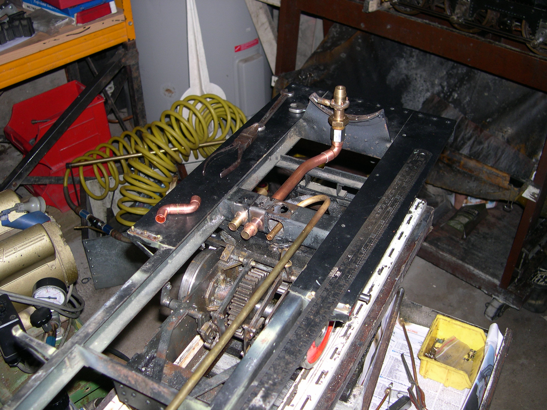
Here is the start of the replacement piping for the front bogie. The difficult job here was bending the 9/32" thin-wall brass steam pipe. This required a home-made pipe bender. There are two exhaust pipes in the left. The leftmost one is a provision for steam from the rear bogie. Currently the rear bogie exhaust from a small chimney in the cab. Sending this exhaust to the blast pipe in the smokebox to improve the draught so the boiler will steam better.
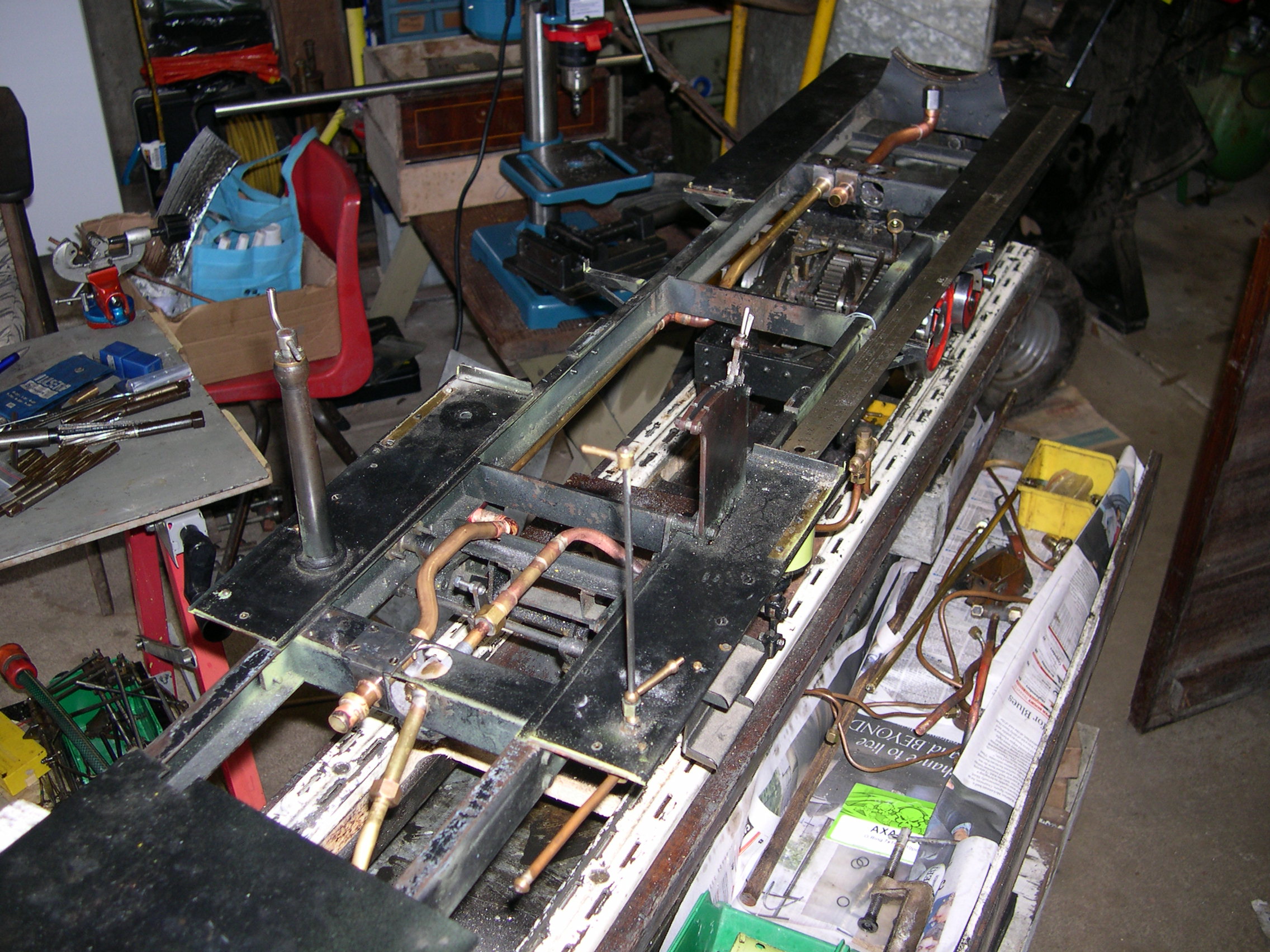
Well, I've decided the rear exhaust should go to the smokebox so here is the rather complicated and wiggly pipe from the rear crossmember to the front one. Now I have to make a Y-connector to go from the front crossmember to the smokebox. This has been designed but how to cut the tubes is yet to be decided. These pieces must be cut accurately enough so they can be brazed together and fit correctly.
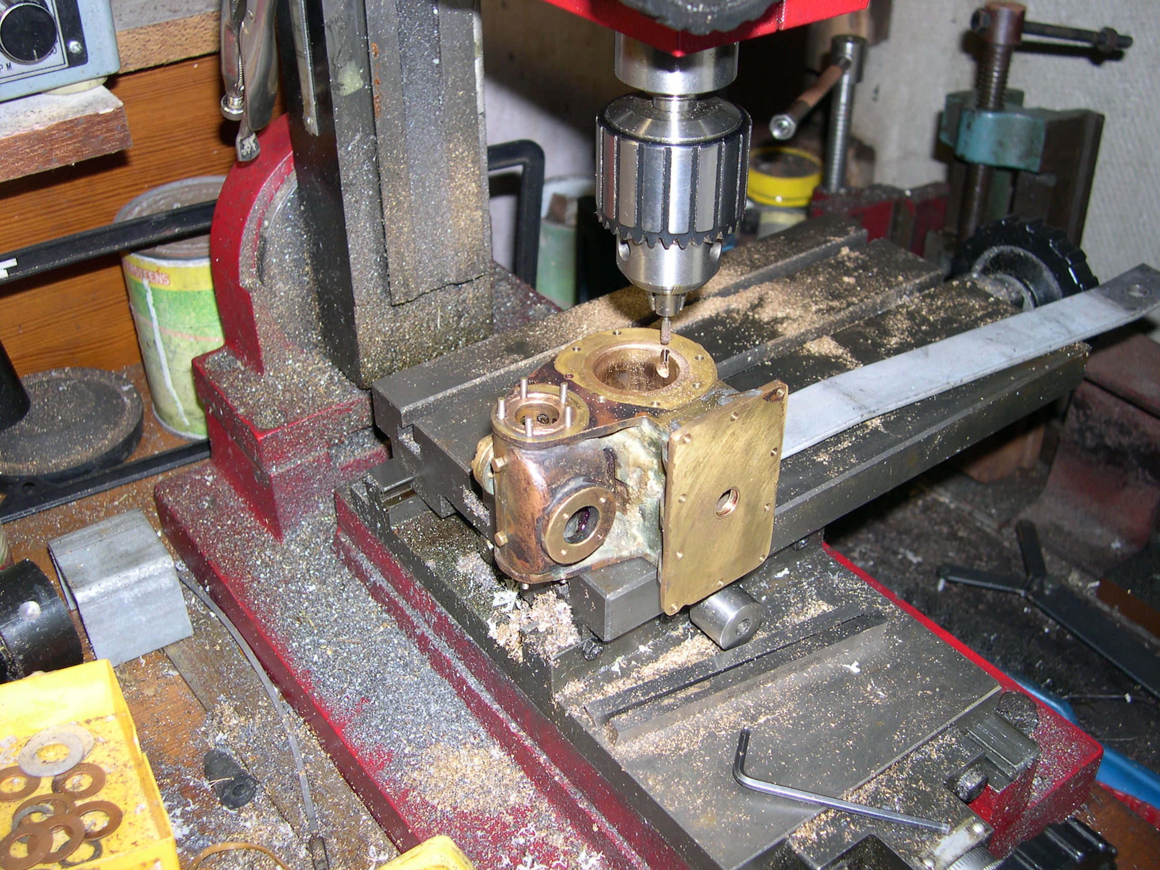
After much pondering about how to accurately cut the long notches in the pipes so I could join them I decided to try using the milling machine. Marking the pipes and setting them up took ages as is often the case. The metal removal went okay and fettling with a file finished the job. The pieces are now brazed together and installed ready for a test.
In this picture I'm trying a flexible pipe as the supply to the front bogie. It is only a household water pipe and I'm testing the bogie using compressed air. If I can find a suitable pipe for steam this might be a good alternative to two ball joints and a sliding joint as used on real locos. Hopefully technology will save the day here.
Also in this picture is the lubricator on the far side. The drive comes from an eccentric on the front axle. The strange shape is to provide space for the steam pipe from the boiler. The original idea for the steam pipe route has been changed to allow for lubricator lid removal.
Here is the front bogie with the new exhaust cross pipe fitted. Rather than using the flanges to seal against the cylinders the pipe ends have O-rings and the flanges are just secured by one screw to keep the pipe positioned correctly. This one screw is accessible when the bogie is removed. The flanges have four holes for screws and the bottom two are very difficult to access. Now I don't have to bother.
The Y-connector in the middle is made from two 3/8" long bends from Ben. I cut half of one leg away on each and braze the bits together to make the Y-connector. The outlet has a pipe fitting for the silicone flexible hose that will be fitted.
The steam pipe is underneath the exhaust pipe and the steam is supplied via a flexible pipe from the front crossmember.
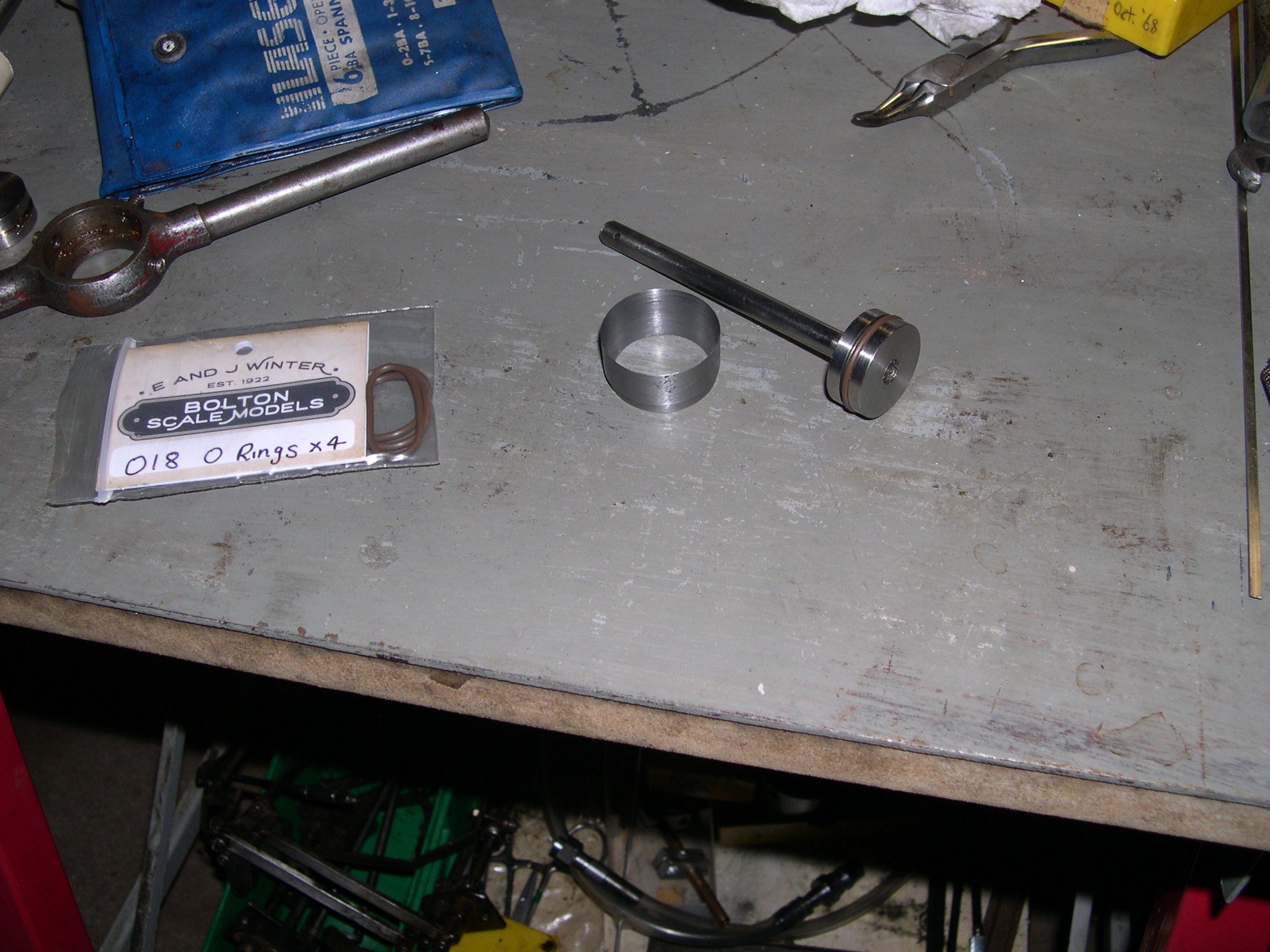
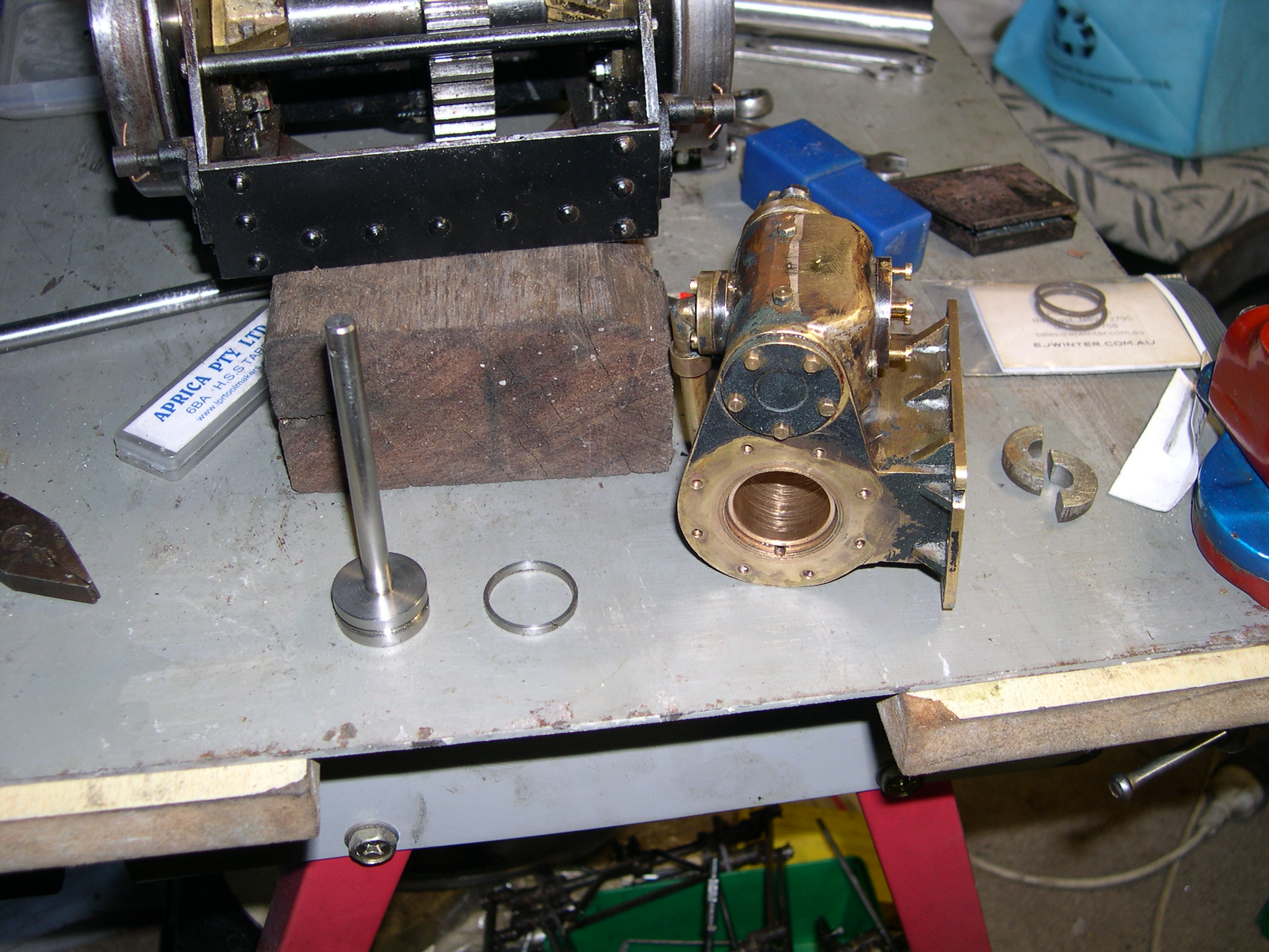
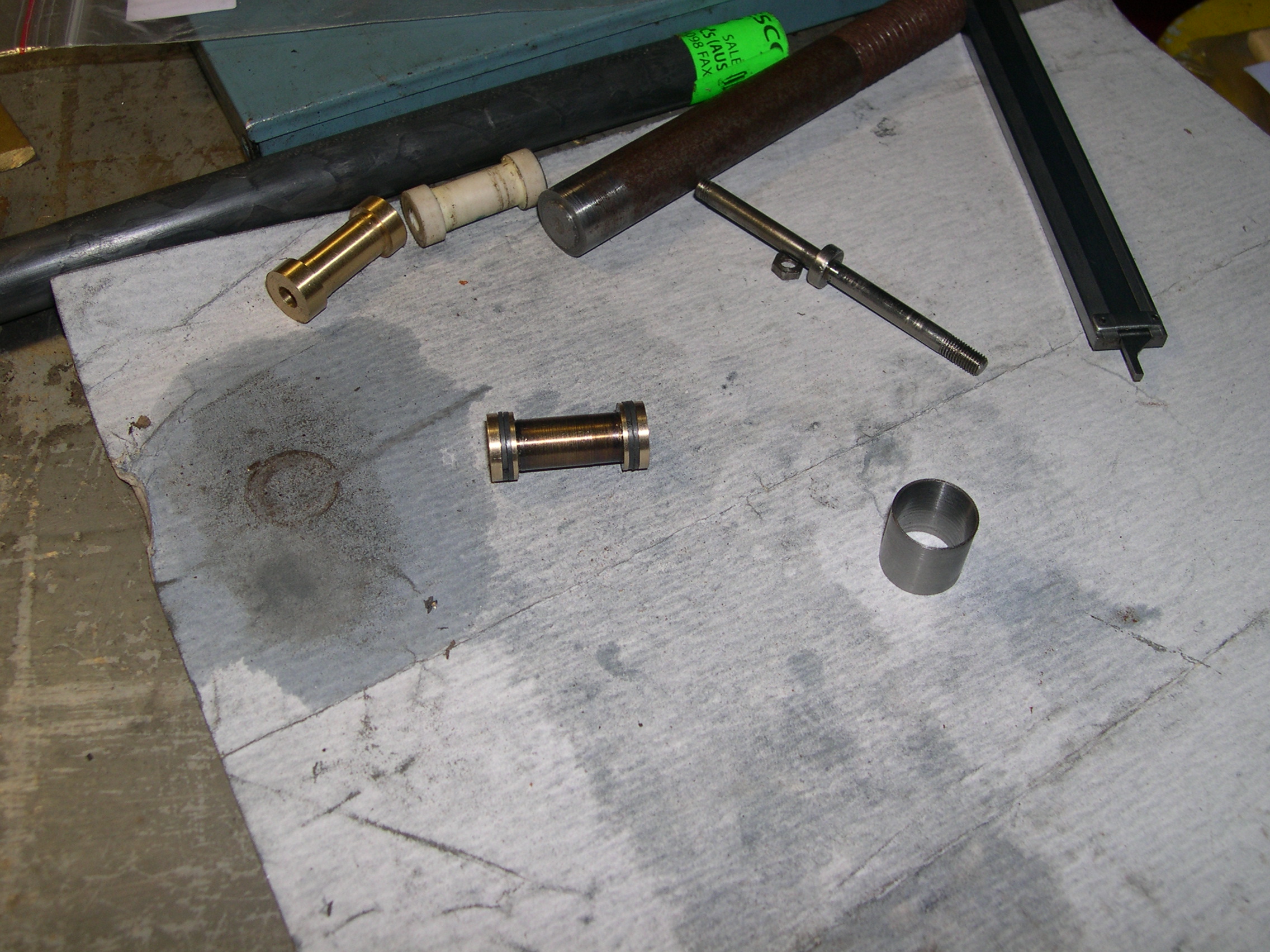
The cylinders are 1" bore and the piston stroke is 37mm. The issue with the bores is that the cylinder ports start at 4mm from the end and extend to 7mm. This means the piston packing will encounter these ports at each end of the stroke. My solution is to fit liners and drill diagonally from the ends to the existing ports. For liners I use bronze bushes that are 1" OD and 7/8" ID. The first picture shows a bush on a mandrel so I can file/sand the outside so it will fit in the existing bore. The bushes are about .004" oversize and the bores are very close to 1". The second photo shows the setup I made to push the bush into the cylinder. This setup turned out to be redundant as pressing the bushes in seemed risky so I made them a slide fit and secured them with Loctite.
Here is a cylinder with the bush fitted and the port opening at the top. The opening was made using a tiny burr in the milling machine. The final operation was to ream the bushes. I bought a 7/8" hand reamer and had this held in the vice. I then rotated the cylinders by hand and they slowly slid down the reamer as any excess metal was removed. I'm not sure this was a good idea as the finish wasn't great. I subsequently polished the bores using very fine sandpaper which did improve the finish.
For the replacement pistons I used some 7/8" stainless steel bar. I decided to use a 7/8" Viton O-ring as the seal. As recommended the groove is .055" deep and .092" wide. The first picture shows the new piston and the cone used to push it into the cylinder. Although the O-ring slides once moving it does stick when the piston stops. So I dropped the O-ring idea and made a piston ring from stainless steel. The bore is 22.2mm and the ring was made to 22.5mm before cutting the gap. Although the groove depth is .055" I found a ring depth of .050" made the ring too rigid and it distorted when stretched over the piston. So a replacement with a depth of .040" was made and this can just be stretched over the piston. Notice the scratches in the bore. I thought the reamer had done these but the reamer didn't rotate this much when cleaning the bore. So, who knows what happened here.
This shows the linkages to the front bogie. The diagonal link on the right is from the reversing lever and controls the lifting arms just behind the front crossmember. The link inside the right channel of the frame comes from the drain cock lever next to the reversing lever. The drain cock link extends forward of the crossmember and works arms and links and finally the kinked link to the back of the bogie. This turns the vertical shaft between the cylinders and this moves the rods to the drain cocks.
The original drain cocks are little safety valves from coffee percolators. This might be good in some ways but it will be hard to heat the cylinders when first starting a run. Drain cocks are often in a vulnerable position and get broken by a derailment. This is worse here because the cylinders are so low and there is no nearby wheelset or guard to protect the cocks. So I'm trying an idea where the cocks have a transverse tube that is normally blocked by a rod. Retracting the rod will allow the water to escape horizontally away from the loco. I'm trying to avoid having the frail cocks and bent tubes that most locos have. The transverse tube has a 3/32" reamed hole and the rods will be 3/32" stainless steel. Any leak here should be insignificant compared to the leak past the pistons and valves. The picture here shows the first attempt at making the cocks. This showed the concept will work but highlighted that the holes for these cocks are not vertical and not even consistent. This means the real cocks will need to be custom for each hole.
As usual with these powered bogies the major issue is arranging the linkage for these cocks. Because the cocks are just open or closed the compensation for bogie rotation is not as critical as that for the reverser linkage. But still it has to be fairly good.
The control lever is next to the reverser lever and works a cross arm for the rear bogie and a rod forward to a cross arm for the front bogie. These cross arms work centrally positioned rods to levers and rods on the bogies that rotate a vertical shaft between the cylinders. The shaft moves a crank that retracts or extends the rods that fan out to the drain cocks.
The final piece in this jigsaw is the actual drain cocks. Rather than the normal conical or ball valves I'm trying a new approach here. The body has a cross tube that is normally sealed by a stainless steel rod. When the rod is retracted it uncovers the vertical hole from the cylinder and lets the steam/water escape horizontally outwards away from the loco. The cross tubes were originally reamed 3/32" (2.38mm) but I had to drill them to 2.4mm to suit the stainless rod. It seems that SS rod available now it actually slightly oversize. I subsequently tried some K&S SS rod which is precisely 2.38mm but it was too hard to drill. The rods have a 0.8mm hole in the end for the connecting SS wire that goes to the eye at the central crank. The crank is rotated by the linkage. The SS wire can flex slightly to accommodate the difference between the arc movement at the crank at the reciprocating movement at the cross tubes.
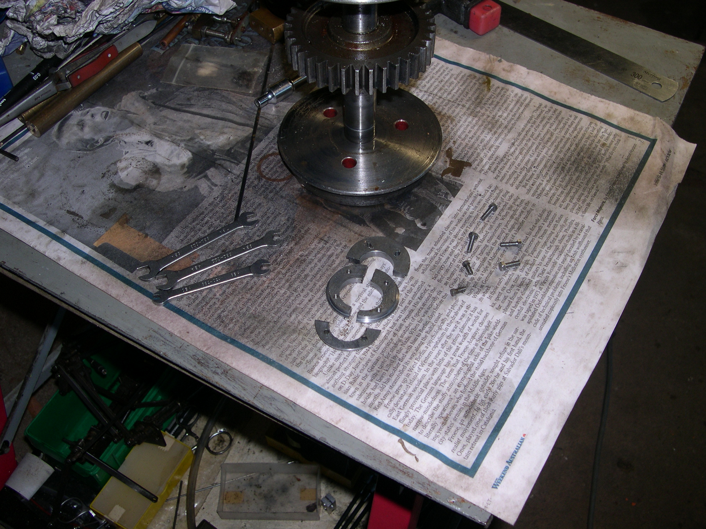
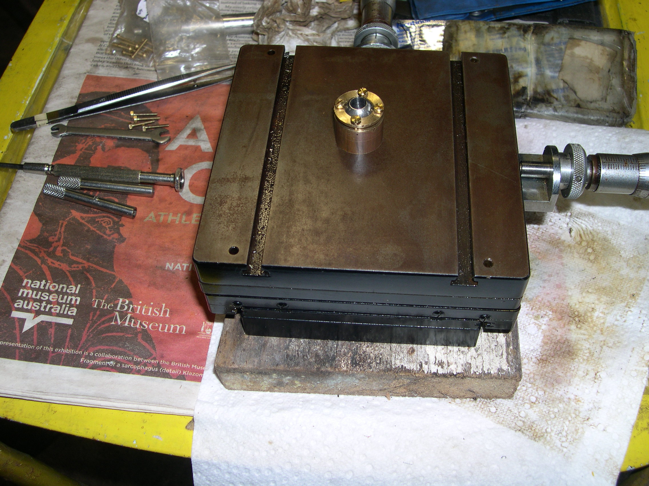
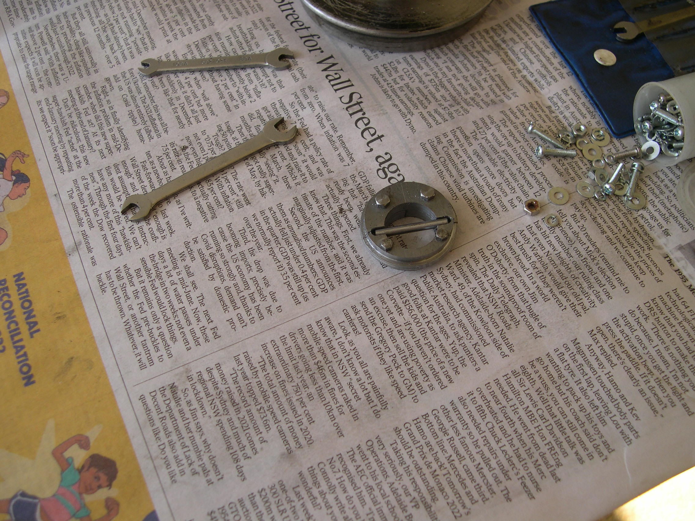
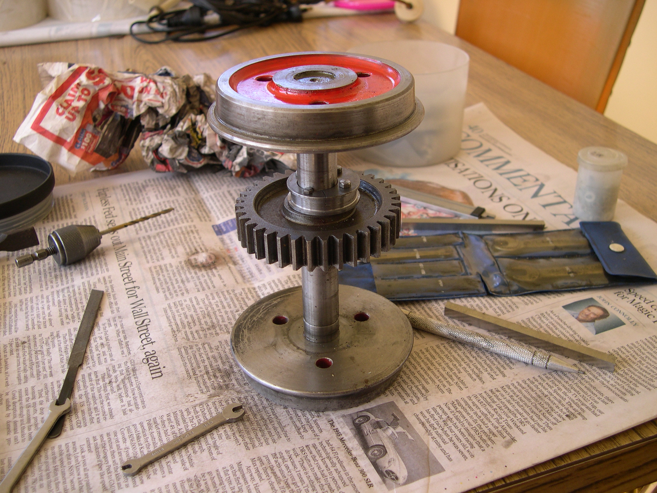
The loco needs a mechanical lubricator and this must inject the oil into the main steam pipe so the flexible joints before the cylinders get lubricated. This presents a problem getting the motion from the bogies to a lubricator mounted on the main frame. Also, getting the motion from the crankshafts is bad because they will spin much faster than the wheels on a normal loco and the lubricator will empty quickly. I've decided to get the motion from an eccentric on a wheelset axle. To fit such an eccentric without removing a wheel and maybe the gear from an axle a split eccentric must be used. There is little room for the boss on a normal split eccentric so the solution is for the eccentric to have a back section with a left half and a right half. Then there is a front section with a top half and a bottom half. These pieces are held together with set-screws. The axle has a cross pin. The back sections don't have a recess for this pin and this keeps them behind the pin. The front section pieces have a recess which stops the eccentric turning on the axle.
The cam follower has a tiny ball race that touches the eccentric mounted on the wheelset axle. This should reduce wear to a minimum. The top of the follower has a Heim joint for the rod that works the lubricator. The first picture shows the follower in position and the second photo shows how cramped things are with the drain cock linkage back in place.
Here is the lubricator (unfinished) installed to check it will fit as planned. The clearance from the boiler barrel will be sufficient to remove the lid. The steam pipe to the front bogie will be above the reverser rod next to the lubricator. So it looks like things will fit so long as I don't need to install anything else in this area.
One design consideration with this project is that things must be as accessible as possible for maintenance. It should be just possible to remove the lubricator with the boiler in place but if not it will require dropping the front bogie and removing the lubricator from underneath. Not ideal but in this case I might be snookered.
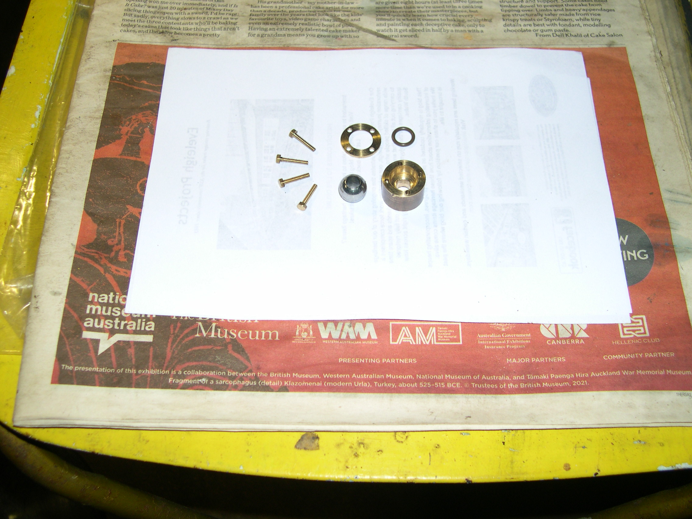
The lubricator has an oscillating cylinder pump with a pipe to the outlet hole at the back of the tank. I was going to put the check valve in the tank but any leak at the connection would result in condensation in the oil. The check valve now screws into the fitting at the back of the tank. The drive hub fits in the hole in the tank side and must be removed to access / remove the pump.
The pump ram is 1/8" diameter and has a 6mm stroke. The eccentric causes the pump spindle to rotate one revolution for each 36 wheel revolutions. Since the wheel diameter is 90mm the pump will work faster than on a normal locomotive.
The pump leaked when first tried and testing with compressed air showed the leak came from the mating faces of the cylinder and base. I lapped these again and this reduced (but not eliminated) the leak. Bench testing showed it was easy to pump the gauge off the dial and that the check valve works well enough to minimise any back flow. Now the lubricator has been installed in the loco and works well enough to pump transmission fluid (much thinner than steam oil) to a pressure of over 1MPa even at slow speeds.
While waiting for some supplies I decided it was time to test the boiler. The first tests were to check for leaks and injector. The clack valves had an O-ring and although this should seal with pressure it often leaks when the boiler is cold. So I removed the O-rings and pressed the ball against the seat to hopefully get a good seal. Hammering the ball (using a brass drift) doesn't seem to work so I put the valve in the vice and use this to push the drift and ball.
But I couldn't get the injector to work. The setup here is less than ideal because the delivery pipe has so many bends. I suspected the clack valve might not allow sufficient water flow so I changed the innards to improve this. However sometimes the valve stuck open so I changed the seat from flat to a 60 degree cone and this fixed the problem.
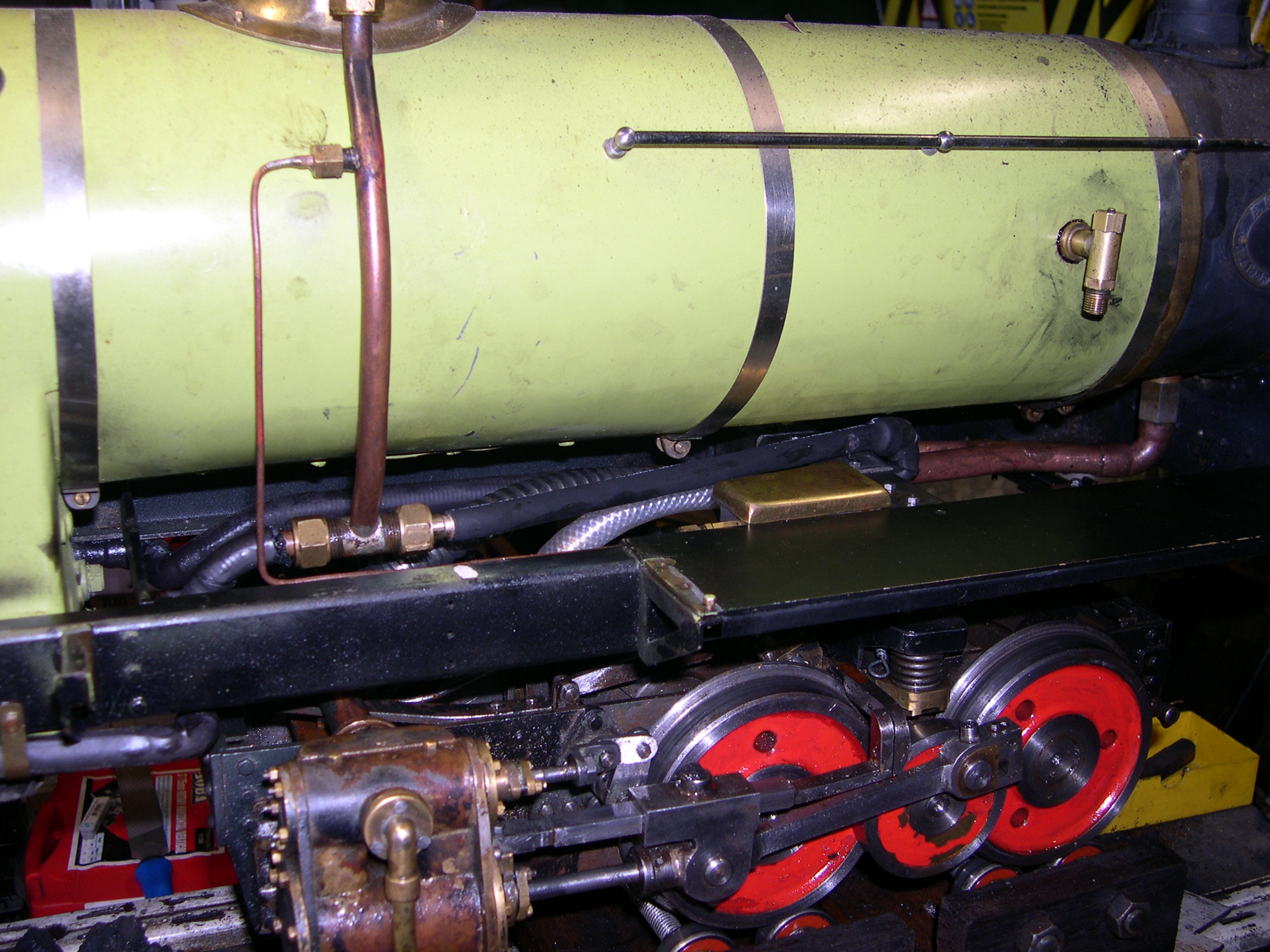
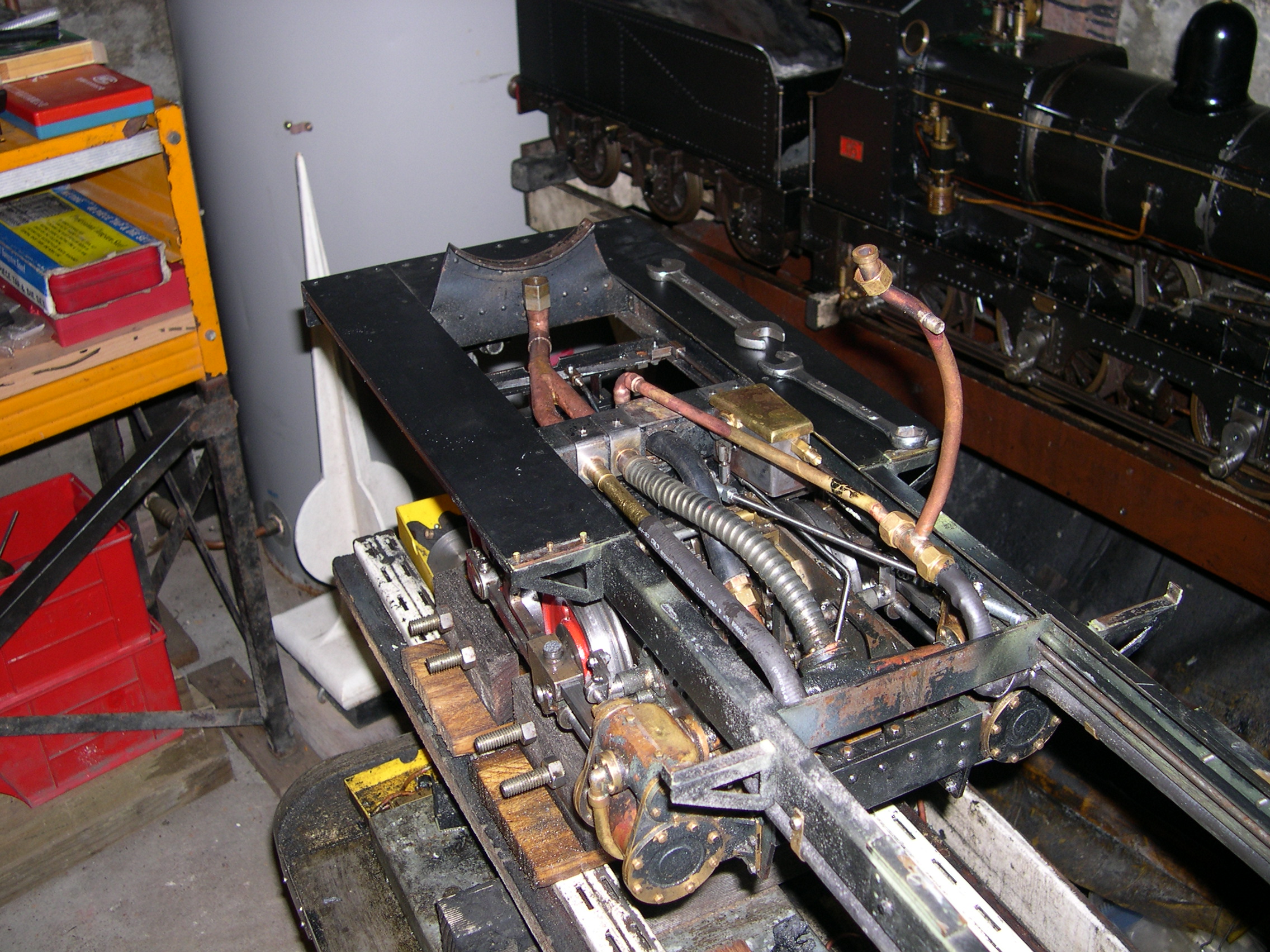
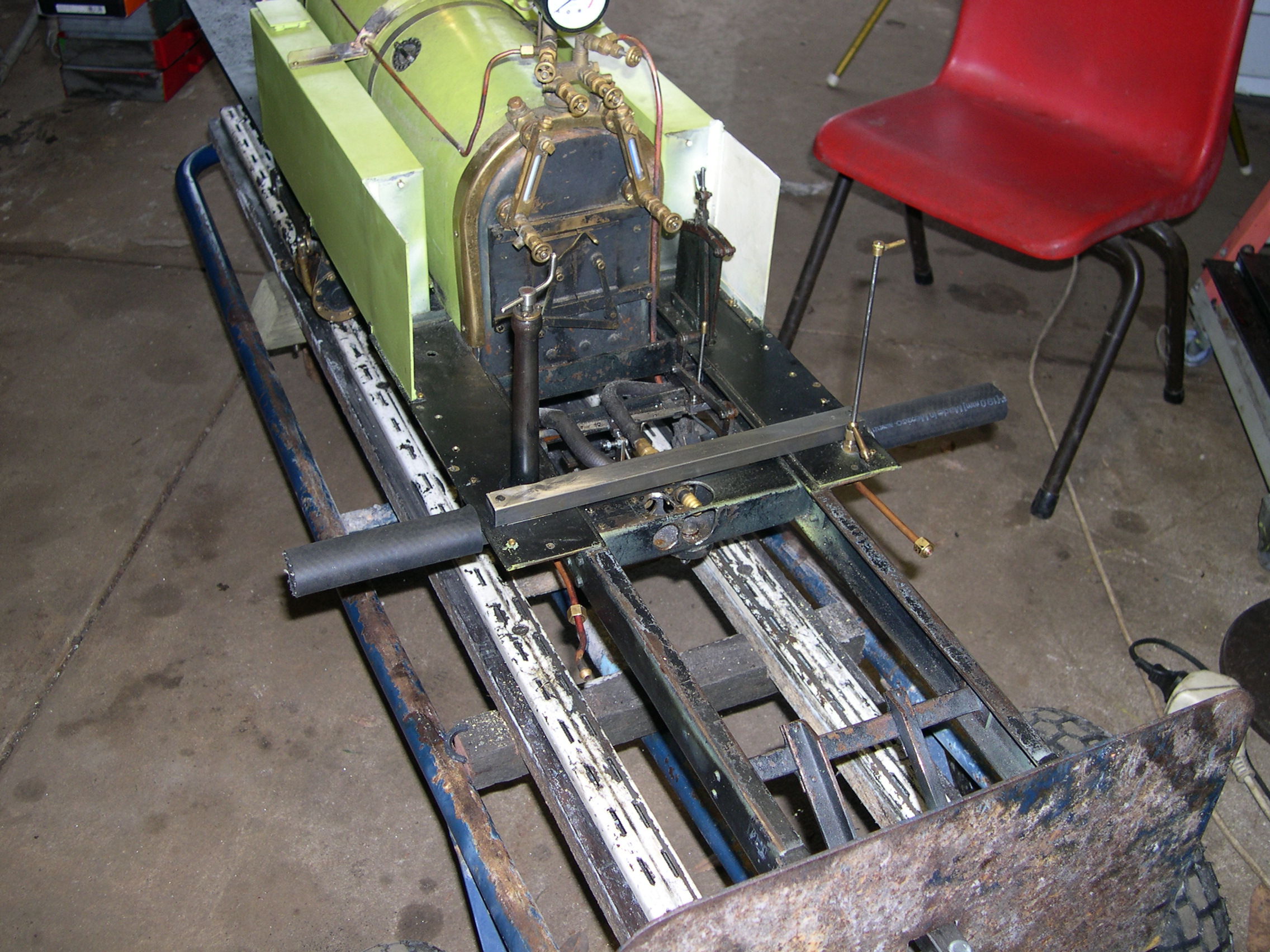
The left picture shows the piping from the boiler to the front bogie. The black pipe takes steam to the U-bend in front of the crossmember. From here the clear pipe is reinforced silicone tube that takes the steam to the cylinders. The lubricator (with the brass lid) pumps oil to the main steam pipe so it will go to both bogies. Hidden behind are the exhaust pipes that go to the copper Y-connector and then to the blast pipe. The steam pipes are covered in heat-shrink tube as an insulator. This picture reminds me I should cover the short main pipe.
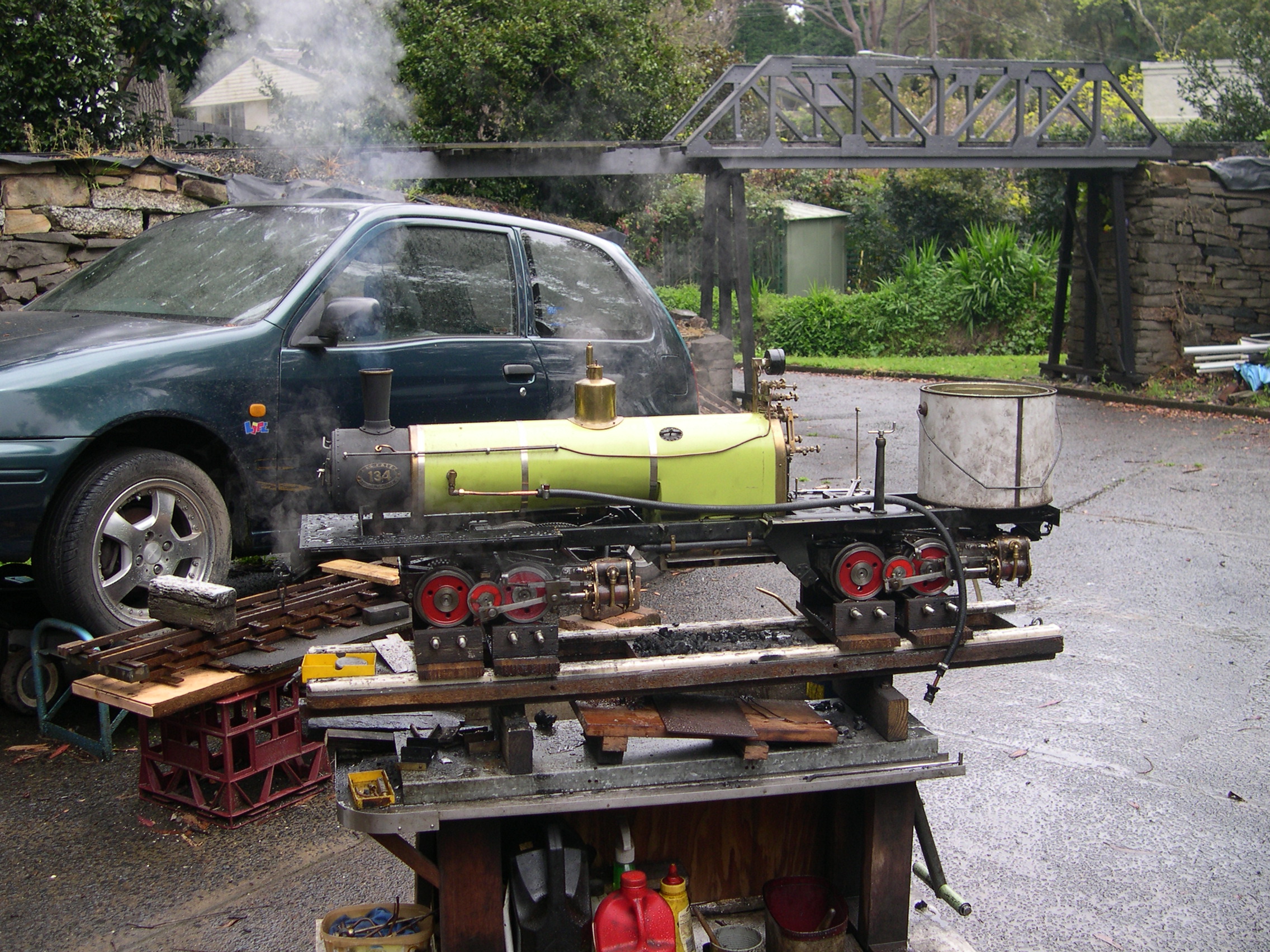
The right picture shows the first full steam test. The loco is on the test rollers so the little wheels can spin. The white tank at the back is the temporary water supply for the injector. There is a big steam leak from the front bogie because I forgot to tighten some of the exhaust connections.
One good thing about this loco is that it's easy to drop the ash-pan and grate. This is useful in an emergency such as low water due to injector failure. During recent testing I've had to kill the fire due to various failures. Normally I just block the chimney and turn the blower on full which works very well. If I'm ever stuck without something to block the chimney I can just pull the ash-pan pin and drop the fire.
For the second steam test I've fitted the bunker tank and refitted the piping. The bunker tank has a hand pump which I can use if the injector fails. The injector has been cleaned in vinegar since the last test and worked well enough this time. It's still a bit fussy for my liking. No serious problems occurred during this test and the next test will be a track test.
During the first steam test we found that the injector wouldn't work reliably if at all. Different injectors were tried and most wouldn't co-operate. The clack valve was modified to allow a greater flow and we also tried a different water supply in case the standard piping was allowing air to get in the supply. The steam valve had a leak which didn't make testing any easier.
The delivery pipe from the injector to the boiler was a long length of 3/16" copper tube with many bends. Each bend imposes a significant impediment to the free flow of water. So the next step was to replace this pipe. The 3/16" tube has an internal diameter of about 2.9mm. The bends had a 12mm radius. The tube size is restricted to 7/32" by the union nuts on the injector and clack valve. The replacement piping uses 7/32" thin-wall brass tube, 1/4" long copper bends, and a bent length of 1/4" copper tube. The minimum ID is 4.8mm and the bends total is about 320 degrees versus 540 degrees with the old pipe. The new pipe twists behind the main steam pipe making it harder to access.
The good news is that the new system works a treat. The injector starts easily and reliably and fills the boiler quickly. Perhaps the standard 3/16" delivery tube with a 24oz injector is a bit small. The system now has a 5/32" steam tube, 3/16" water tube (both original), and the new 1/4" delivery tube. The left picture show the old pipe and the right picture shows the new pipe.
The first test run was plagued by injector problems and I blew the heatshrink tubing sealing the rear flexible exhaust pipe on the second lap. We did a quick replacement with double thickness heatshrink tube but this also blew. Definitely not a good idea. Also we noticed the loco used far too much steam due to a bad blow somewhere. This was the first time the loco has ever run.
For the second test run I fitted the tanks, cab, and footpegs so the loco is almost complete. It has the new injector and piping and this worked well. The flexible pipes for steam and exhaust are the new silicone tubing and these also worked well. But the loco still used far too much steam and the boiler couldn't keep the steam pressure for more than one lap.
The third test run was to test the steaming changes. The ash-pan has been removed because it is very shallow and fills quickly and blocks the air supply to the grate. The blast nozzle has been replaced by a smaller (5mm) and higher one so we have the 1 in 3 cone to the chimney throat. The blower has been replaced by a simple bent length of 1/8" tube. On this test the loco kept steam even when the boiler was getting thrashed and the fire was littered with clinker. So, total success here. The major outstanding issue is the severe steam blow due to leaking piston valves. This increases the exhaust back pressure which kills performance. And the loco uses far more coal and water than it should. However, things are looking up.
The fourth test was a total failure. I'd made some new bobbins for the piston valves using Vesconite HiLube which is a Teflon-impregnated plastic. These bobbins were undersize to allow for expansion when hot. I figured the temperature would be about 150 degrees and calculated that 0.0028" clearance for expansion would be enough. So the bobbins were a sloppy fit when cold. But as soon as I applied steam to warm the cylinders the bobbins jammed solid. Moving the loco would strain the valve gear. When I let the cylinders cool the bobbins were free again. But applying steam again caused them to seize. My idea of using plastic valves seems doomed. This is a shame because they could seal very well if I could get them to work.
The fifth test was using the newly made brass bobbins for the piston valves. There is still a steam blow but better than before. I think the only way to improve this is to make bobbins with some kind of sealing rings.
The loco steams well now and the new super-powerful blower is great if I have to wake the fire up quickly. The valves don't seem to be set quite correctly and the cut-off is a bit short because in full forward gear the expansion links hang too low (they should be at least 2mm above the rail head).
There is slop in the valve gear which also doesn't help. I might have to make some new die blocks and maybe expansion links to tighten up this area.
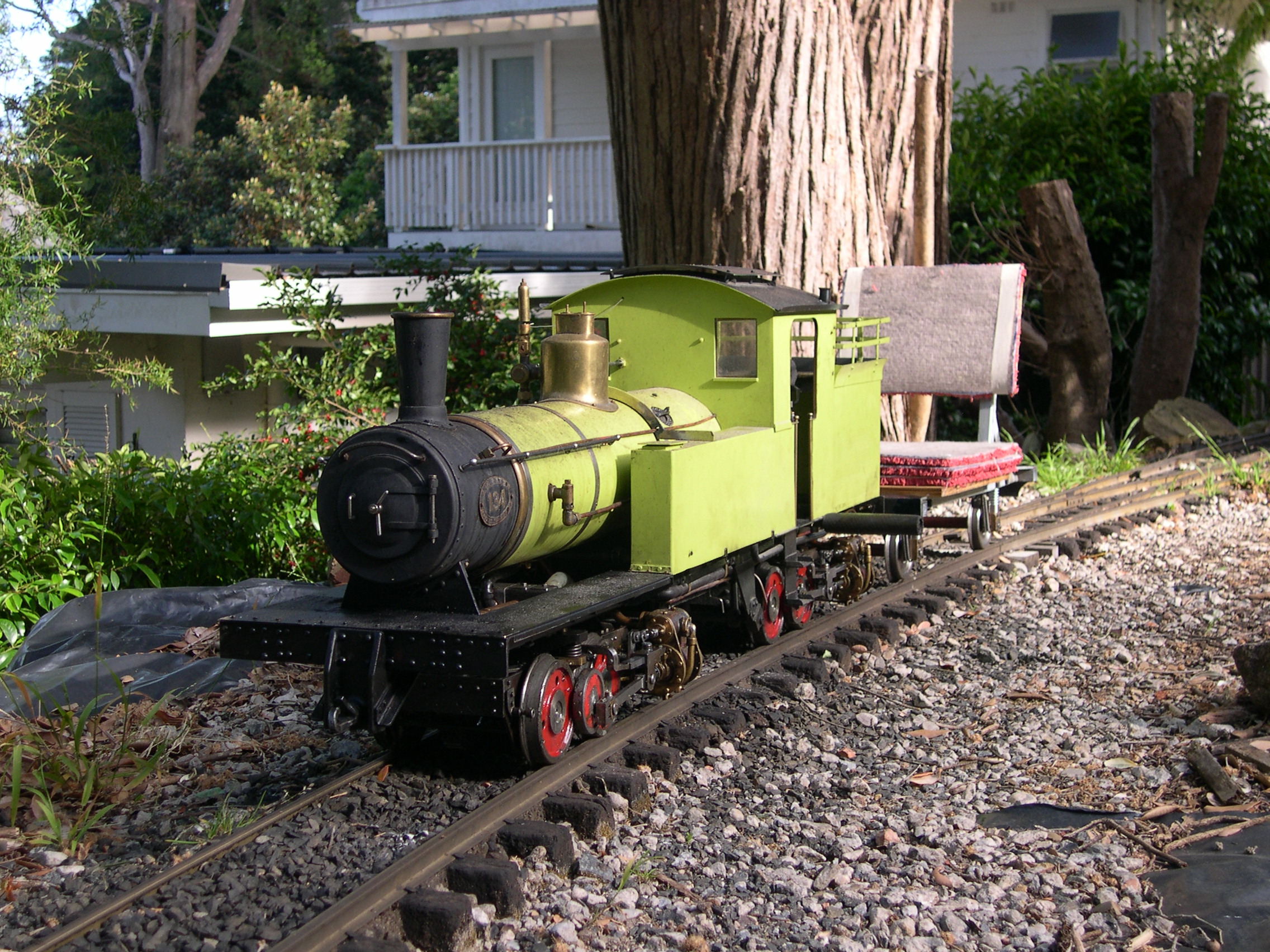
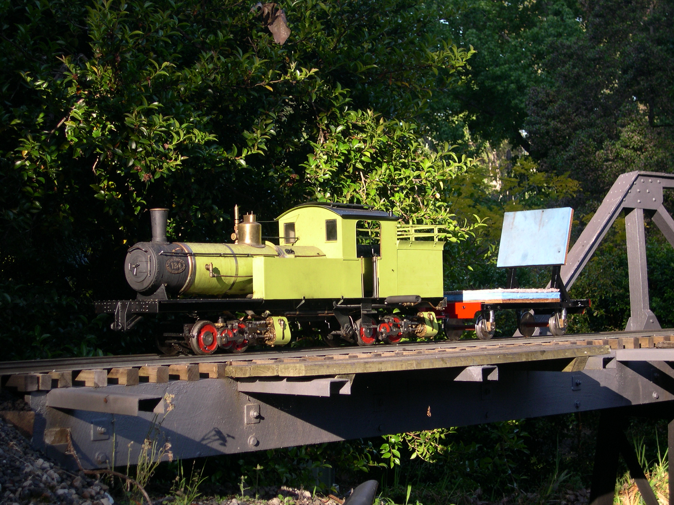
The next test was to check the new bum truck. This has a very low seat so I can see under the cab roof more easily. The only reason I now need to lift the ventilation hatch is to see the pressure gauge. The idea here seems good but the loco ran like a dog on this day.
When I re sleeved the cylinders I made new pistons and rings from stainless steel. The drag from the rings was excessive so after yesterday's miserable performance I made some plastic rings using Vesconite. Although this expands less than some plastics when heated it still expands about four times that of brass. So the rings need a large gap (1mm) and I had to fit two rings with the gaps opposite in each groove. The good news is that on the next test these new rings sealed well and offered little resistance so the pistons moved much more easily and the loco trundled around like it should.
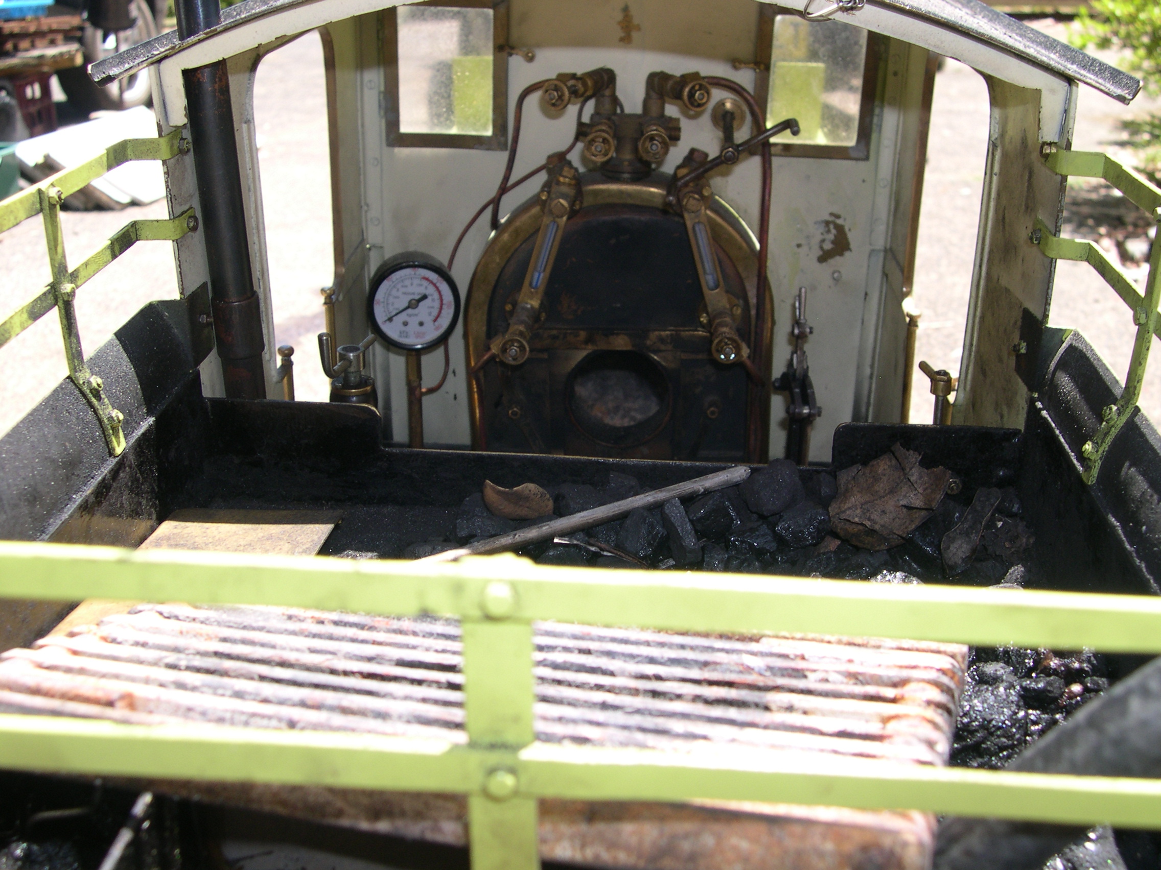
The pressure gauge was mounted just under the cab roof and I had to lift the ventilation hatch to see it. I've now mounted the gauge on a post beside the firebox where the displacement lubricator used to be. The issue with this large gauge is that it had a 1/8" BSP fitting on the back. It now has a 3/16"x40 fitting underneath the same as the standard 1" gauges. The gauge screws onto the post via an adaptor.
The last test was plagued with injector problems. I cleaned four injectors for this test. The other possible issue I found was that the tail on the water pipe didn't seal properly. This might allow air in which would definitely cause a problem. The test here showed the gauge repositioning is good and that the second injector we tried works well even on a hot day. The loco ran for hours and this was the best run so far. Yippee.
After my recent success with plastic rings for the pistons I made some smaller rings for the valve bobbins to see if I could reduce the steam blow here. I made a 2mm wide by 1.35mm deep groove near each end of the bobbin. The plastic rings (Vesconite) are 1/2" OD (same as liner ID) with a 1mm square cross-section. To allow for the expansion of the plastic I need a gap of at least .5mm. In each groove I fit two rings with the gaps opposite each other. In total I needed 16 rings. Machining the plastic rod was okay but parting off each 1mm ring left flash and whiskers. Perhaps my parting-off tool (an old hacksaw blade with a ground end) is not ideal.
The test run started with lots of steam to make sure the rings didn't seize when hot then we did a few laps which went well. The steam blow is reduced markedly (probably as good as I can get) and the loco ran much better at slow speeds. The picture shows one plain brass bobbin, a plastic bobbin which was a total failure, and a grooved bobbin with four rings fitted. Also there is a valve spindle and the compressor I use when re-fitting the bobbins. Although the rings are the same size as the bore I assume they will expand slightly when hot and provide the sealing.
The next runs were on the 30th and 31st of December 2022 in a desperate attempt to get a good trouble-free run before the end of the year. On the 30th the loco went well but the injector clack valve played up. Multiple times it jammed open after the injector was stopped. I'd refitted the original cap to this valve and it lets the ball rise too high which is good for the water flow from the injector but the backflow after holds the ball off the seat.
On the 31st I refitted my cap which has an adjustable stop. Because the seat for the ball is a cone (not a flat seat) I calculated I needed 3mm lift for the clear area to match the area of the hole below. I also replaced the ball as the old one appeared to have some divots. On this day the loco ran well for hours only interrupted by a tubes clean because I was using terrible coal that filled the valley with green smoke and totally blocked the tubes. After the clean the loco ran well again and this was a great end to the year.
Last modified 2025-05-26