| Introduction | Modifications (the sequel) |
Contents |
The original mods page was too large so it has been split. This is the page for major changes.
- Banding when auto feed
- Fitting a 4-jaw chuck
- Top slide modification
- Tool support
- Parting tool holder
Banding when using auto feed

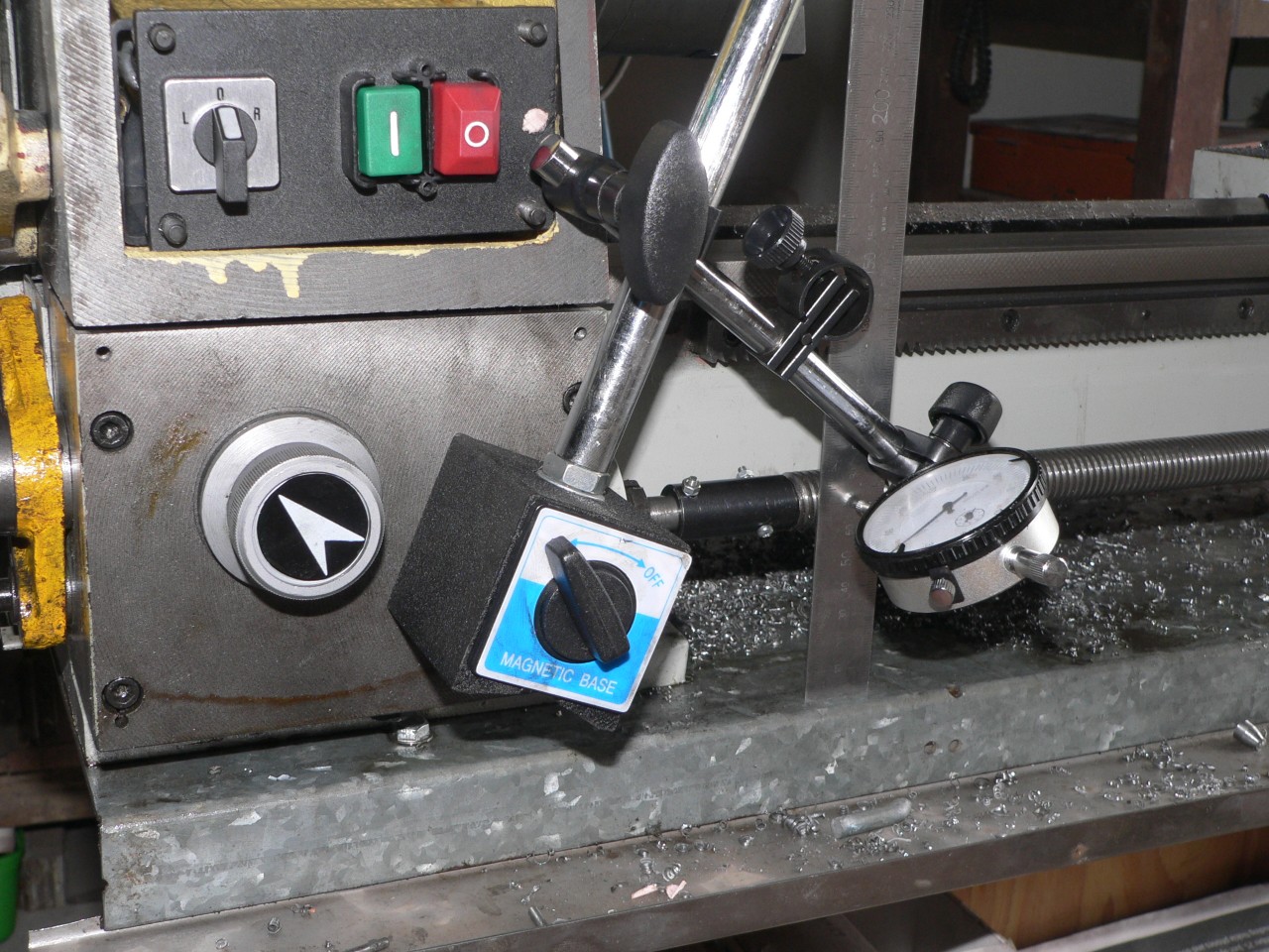
When using the auto-feed the resultant cut has slight bands that are 3mm apart. The obvious culprit here is the leadscrew or perhaps the split nut. Here I am testing the sleeve that connects the leadscrew to the gearbox. There is about 0.2mm run-out and it looks like the gearbox shaft is bent.
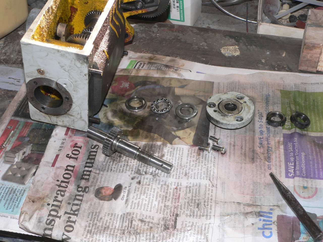
Checking the gearbox revealed that the thrust bearings were too tight and the round nuts were not sitting straight as the one nearer the bearing was past the threaded portion of the shaft. I put a spacer washer next to the thrust bearing and then tightened the nuts to remove the end-play but no further.
The run-out is less than before. I've reversed the sleeve so more is on the leadscrew (tighter alignment) and the short portion is on the gearbox shaft to allow for any misalignment between the gearbox and the leadscrew. The gearbox must be aligned carefully before tightening its mounting bolts to avoid any distorting force on the leadscrew. When it is right the leadscrew spins easily.
The banding problem is better now but still noticeable. I've tried lowering the apron slightly by putting 0.5mm shims between the saddle and the apron but this didn't help. I've also tried removing the supporting bearing at the far end of the leadscrew. Leaving the leadscrew floating like this fixes the banding but is not really a proper solution.
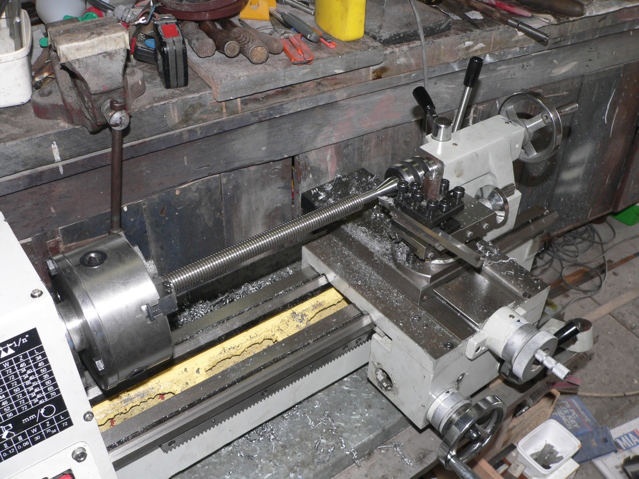
The end of the leadscrew was bent so I machined it until true. This reduced the diameter from 12mm to 11.5mm so I had to make a new sleeve also. To turn the leadscrew I put a thin metal sleeve around the part gripped by the chuck. My new live-centre has certainly earned its keep by now.
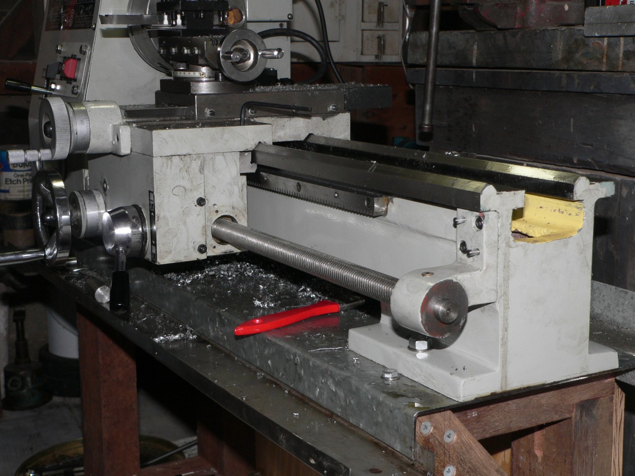
The new connecting sleeve is 60mm long (original is 40mm) and the leadscrew is pushed 12mm towards the tailstock. This means the far end of the leadscrew protrudes from its bearing making it easier to fit a handle here. A handle with a resettable dial and 60 graduations of 0.05mm will be a good feature. The leadscrew pitch is 3mm.

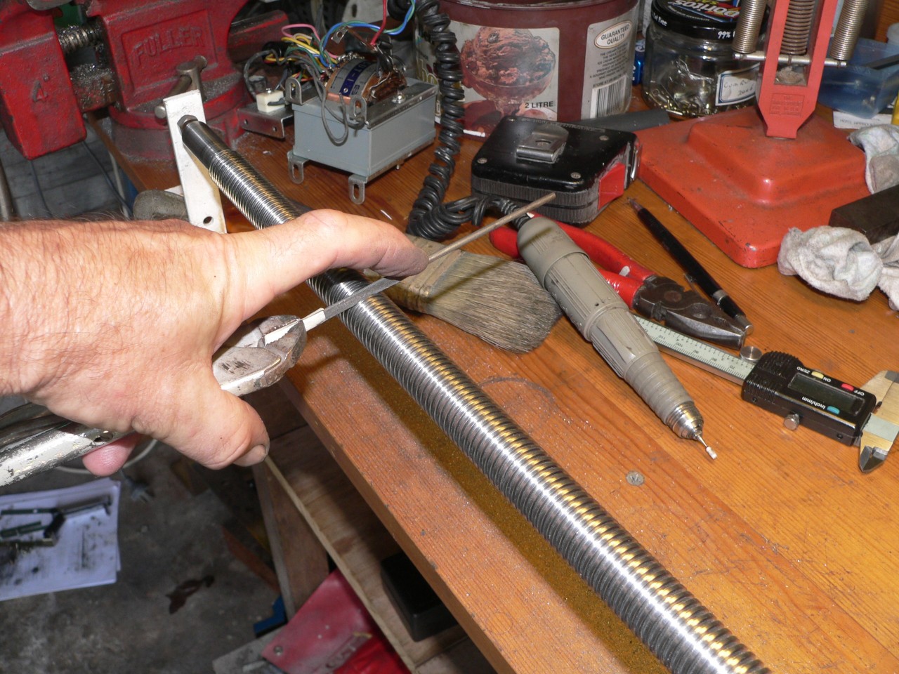
Cleaning the leadscrew was the next step so I made a jig to hold and spin it. There were some rough highs in the thread valleys so I examined the whole thing and filed the highs with a 1mm wide file. Then I used the drill to spin the leadscrew and polished it all with the same file and then with some fine sandpaper. I could feel the rough spots when filing or sanding and the screw is much smoother now. Let's hope I haven't done immeasurable damage and wrecked the thread profile. It a M20 x 3 trapezoid thread (ISO fine) and I checked for a thread chaser or a die nut but couldn't find anything.
The half nuts each have a 6mm pin that connects to the cam wheel. One of the pins looked bent. It turned out that the pin was okay but the hole was skewed. I enlarged the holes, tapped an M8 thread, and made some new pins.
Apart from the apparently skewed hole, the half nuts seem well made. I assembled the nuts and leadscrew on the mill table and everything lined up correctly. A fault here might explain the banding problem.

Initial testing shows no banding so things look good. What doesn't look good is that the bottom half nut is too far away from the leadscrew. The new pins obviously haven't fixed this problem. It's time to check the cam wheel.
The half nuts should be about 3mm apart when clamped on the leadscrew. At the moment they are about 4mm apart when engaged. It's difficult to photograph the error. After seeing how the nuts looked when clamped on the leadscrew I can tell that the position here is not right.

Here is the apron with the half nuts and cam wheel removed. The finish on the bearing hole for the cam wheel is mediocre. The finish on the slideways is rough. The cam slots are 6mm wide and are 20mm apart at the engaged end and 28mm apart at the disengaged end. Since the half nut pins are 17mm apart this means the nuts should be 3mm apart when engaged and 11mm apart when disengaged.
The cam slots were slightly skewed which caused the pins to bind. I cleaned the inside edge of each slot until it was vertical. Any extra play resulting from this will affect the opening of the nuts rather than the closing. The bearing hole for the cam wheel was also polished (heavily). There is now a little play here so the half nuts will be able to centre slightly when engaged.
The slideways (including the dovetails) were polished also until the half nuts slid smoothly. This area was very rough and the polishing made a big difference to the smooth travel of the nuts.
The end result is that the auto feed mechanism is now smooth as silk. It was really gross before. When closed the half nuts are 3.2mm apart (should be 3mm) and this is good enough for me. There is no extra play in the half nuts so the cleaning of the cam slots has fixed the binding without introducing any extra slop. The leadscrew is being lifted about 0.1mm by the half nuts when engaged (probably not a problem) and there is no banding now and the leadscrew isn't touching its guide in the apron.
Fitting a 4-jaw chuck
The last lathe I used was a Myford ML7 and it had a 4-jaw chuck. I cursed this chuck at first because setting up anything is a slow effort compared to just clamping it in a 3-jaw chuck. But after a while I became used to the effort required to centre a job and I began to appreciate the accuracy and versatility of the chuck. So, one of the first accessories I wanted for the CQ9325 was a 4-jaw chuck.
The spindle flange isn't suitable for a 4-jaw chuck because it is an unusual size and there are only three mounting holes. I visited Mick Moyle's in Sydney and bought a 160mm chuck and an old cast backplate that looked like it could be machined to suit.
The backplate was designed to screw onto the spindle so I made a mandrel for machining. The mandrel is made from an offcut of 55mm hydraulic ram which was very tough steel with a hard chrome surface. I reduced a section to 52mm a cut an 8TPI thread. This was hard work; more for the lathe than me. Then I could mount the backplate and machine the face to match the spindle flange. The backplate was easy to machine but that damned cast iron dust gets everywhere and becomes a nasty black abrasive paste.
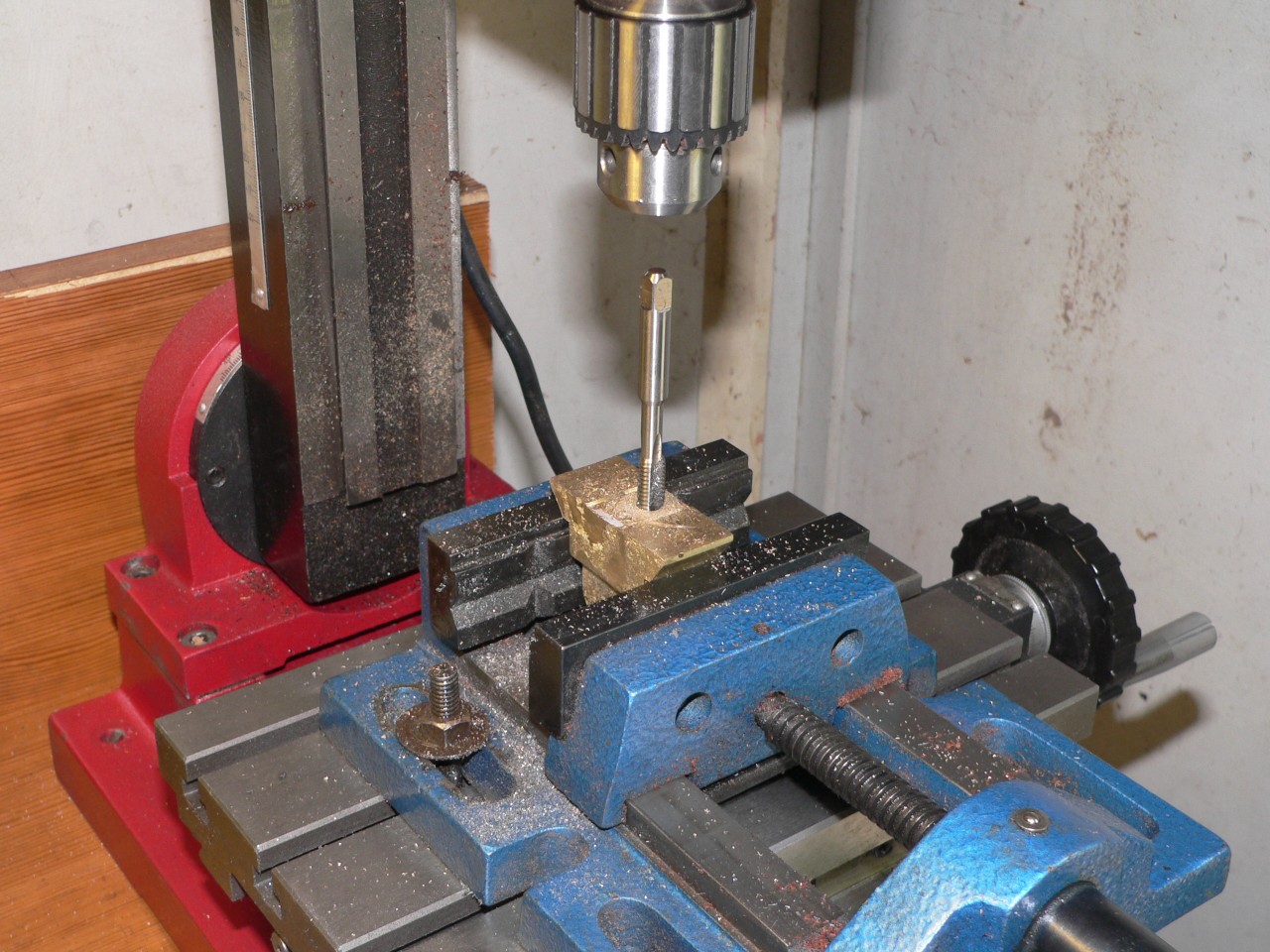
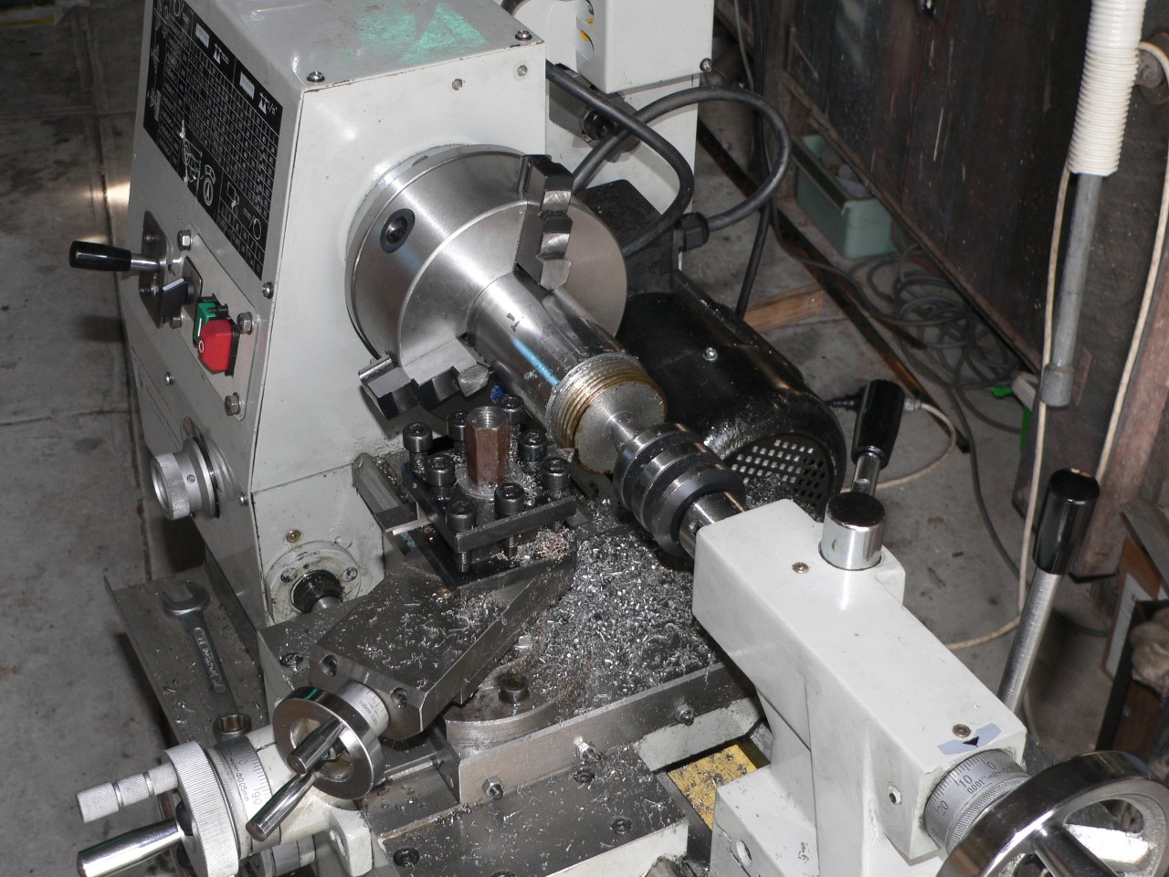
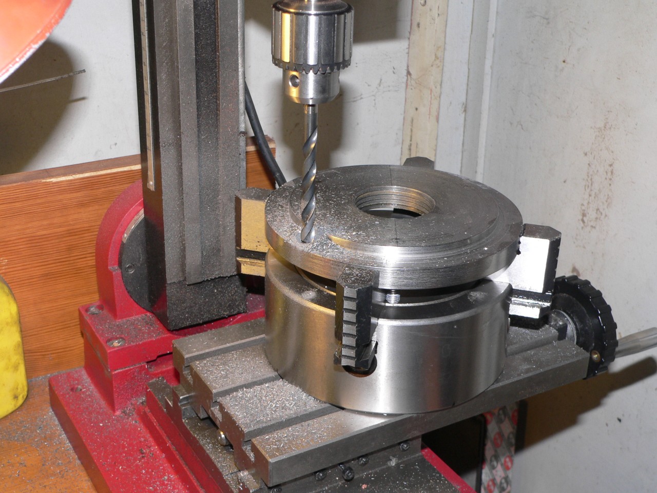
The backplate had a protruding hub which had to be removed before truing the face and making the 100mm diameter recess. Most of the cuts were done using the wrong tool for the direction (e.g. left-hand tool for right-hand cut) to avoid any snatch problems due to positive side rake. For finishing cuts I used a tool with no rake which gave good results but was no good for removing much metal. Finally I used my Mighty Mill to drill the holes for the mounting bolts. I ended up using M8 studs rather than bolts to avoid wear on the threads in the backplate. Although it looks like I am power-tapping in the picture here the mill is only used to start the tap to ensure it is straight.
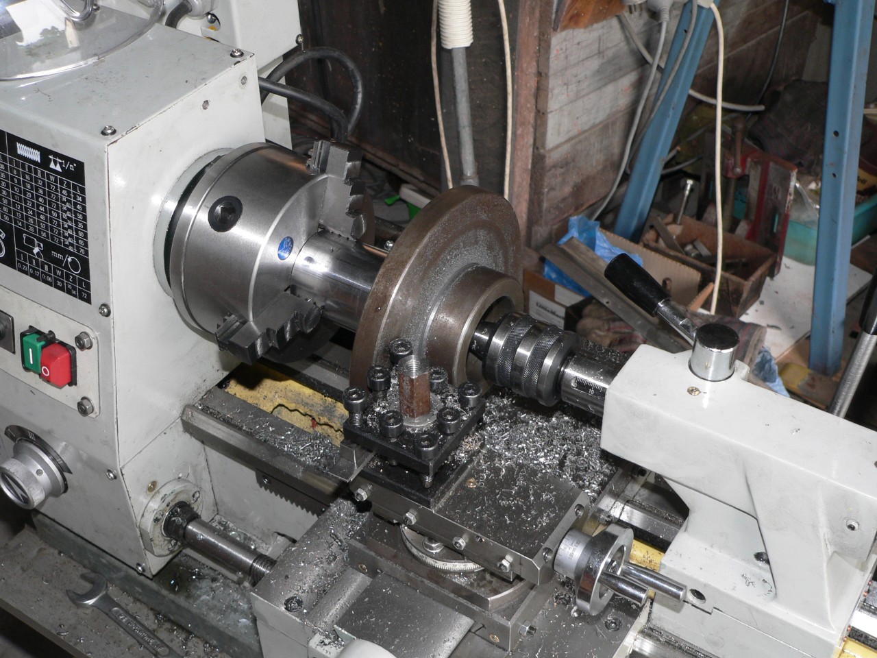
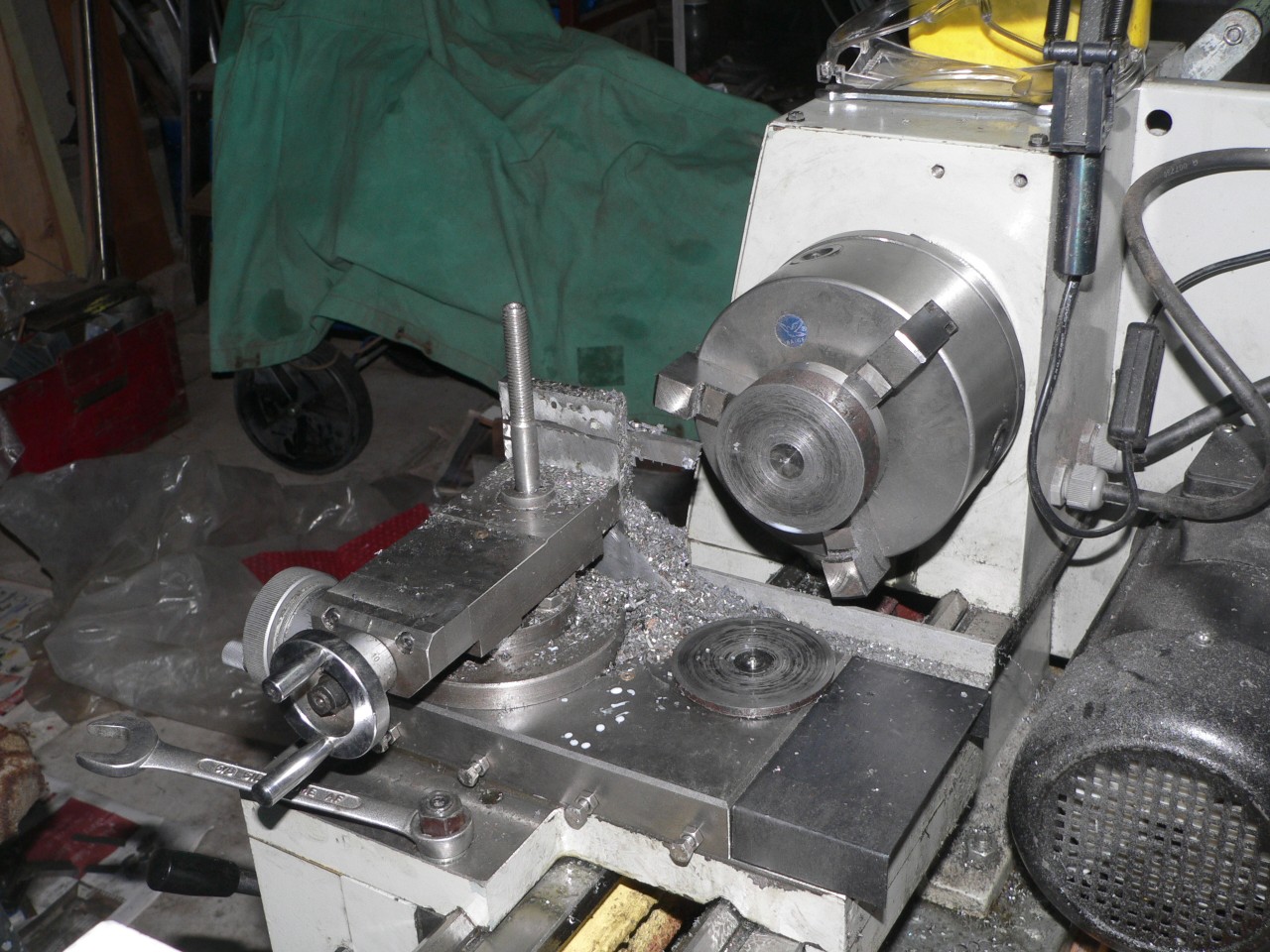
In the second picture the second face of the backplate is now being machined. The cross slide is very close to the job to reduce tool overhang. As before the tool position and cutting direction are set to avoid any snatch because I am trying to be very accurate here.
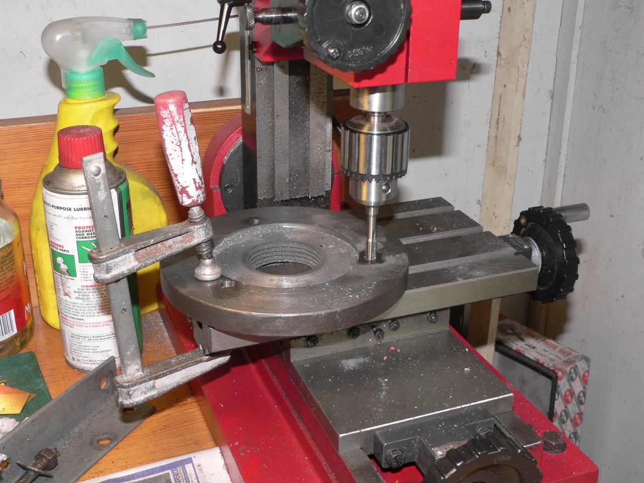
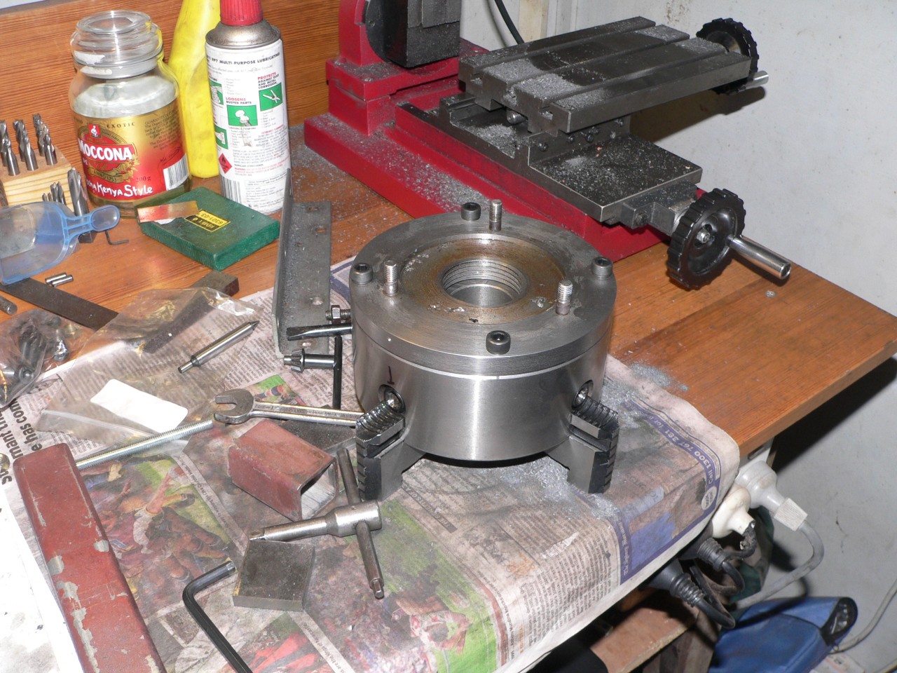
Here is a strange use of resources because I am using the chuck to hold its backplate so I can drill the holes for the mounting bolts. The hard bit here was marking the positions accurately. With the grace of God and a good centre drill the holes turned out well. They are 8mm holes for 8mm bolts so there is no room for error.
The spindle flange is 132mm OD and the pitch circle for the bolts is 145mm so I had to use Allen bolts as hex head bolts would foul the flange. Even so I had to trim the flange down to 131.4mm so the heads would fit. 132mm seems a strange size for the flange as the standard 3-jaw chuck is 130mm but perhaps the extra 2mm gives the flange a bit more strength around the bolt holes. If it fractures in the near future I will know I have done wrong.
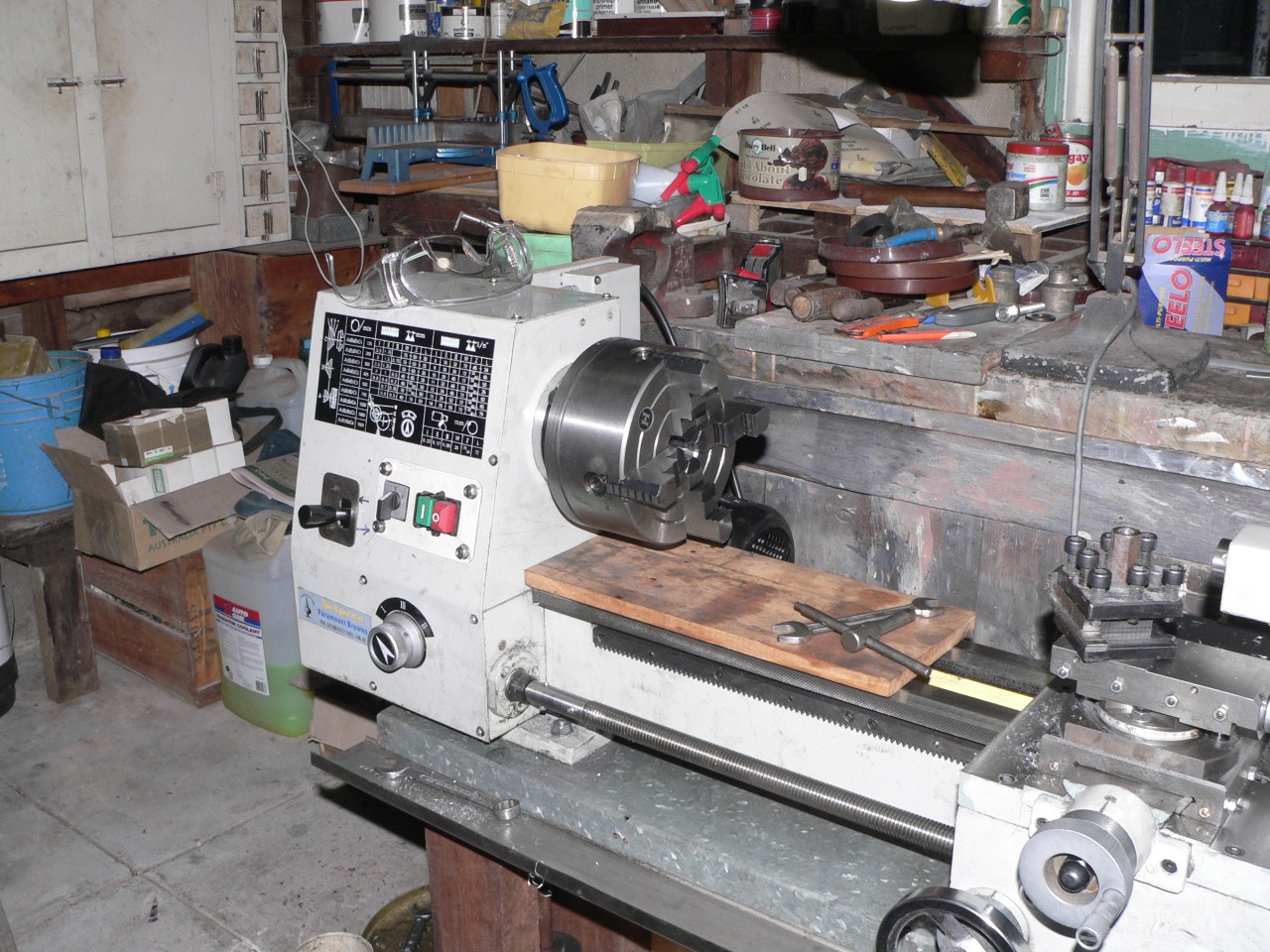
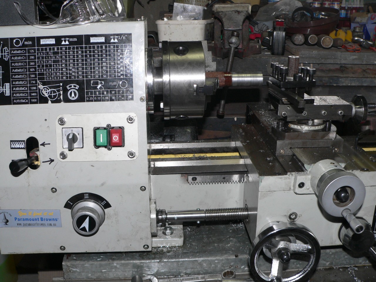
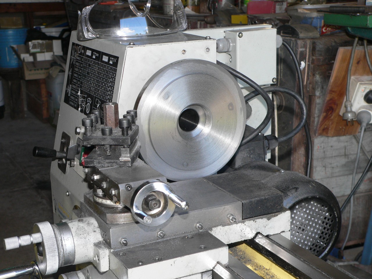
Finally the new chuck is installed on the lathe. It sure does look big for the little lathe but I suppose I'm used to light-duty chucks. The only disadvantage with this chuck is that it fouls the cross slide so I can't move the carriage right up against the headstock when I'm not using it (e.g. when filing or sanding). If I repeat this effort I will get a 150mm chuck that should just clear the cross slide. Also, I would probably use a light-duty chuck as they are thinner and still strong enough for most jobs.
Top slide modification
The top slide has 70mm of travel of which about 60mm is usable. The feed wheel must be rotated carefully or the side force will cause marks in the workpiece. As my feedscrew was slightly bent I made a replacement and changed the design slightly. The top slide body is 110mm long and the base is 90mm so the mid position to maintain maximum slideway contact should be with 10mm overhang at each end. But since the toolpost is at the headstock end I made the mid position when the left ends of the base and the body are aligned. The travel of the new design is 64mm. This means the body will overhang 32mm when fully left (leaving 78mm of slideway contact) and will overhang 52mm when fully right (leaving 58mm of slideway contact with the side force from the tool being exerted in this 58mm region).
There is now a guide at the left end of the feedscrew to reduce skewing of the feedscrew due to side force from the feed wheel. This guide must be removable as the feedscrew is installed from the right. The top slide body has an 11mm blind hole for the feedscrew and I had to make this a through hole so I could install the guide. The blind hole is good because grit can't get in. The through hole should be okay as the guide is a close fit and will push any grit out.
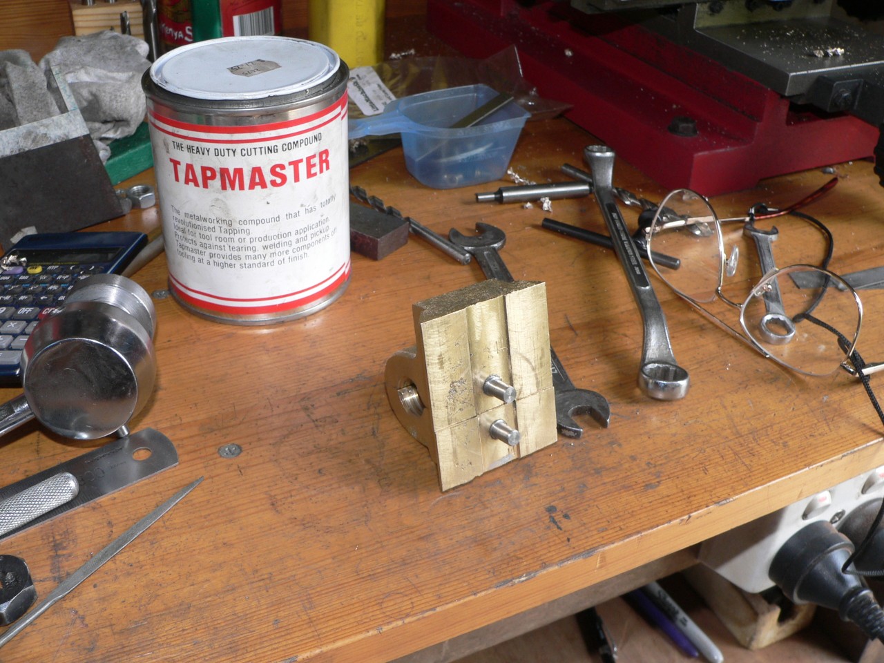
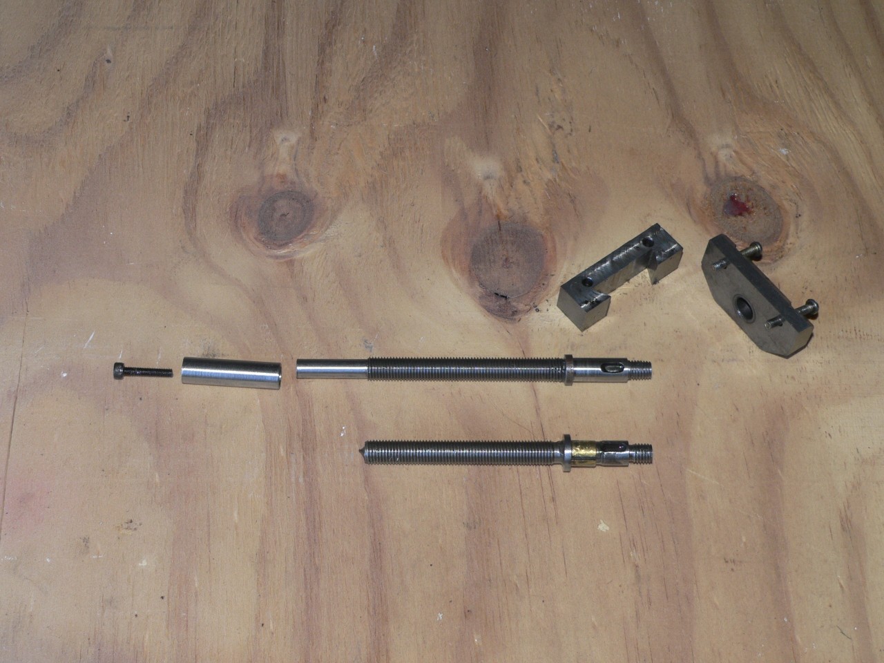
To get the longitudinal alignment correct I had to make a 15mm spacer (complete with sloppy dovetails) to fit between the body and the right side plate. The picture here shows the original feedscrew and the replacement with its guide and spacer.
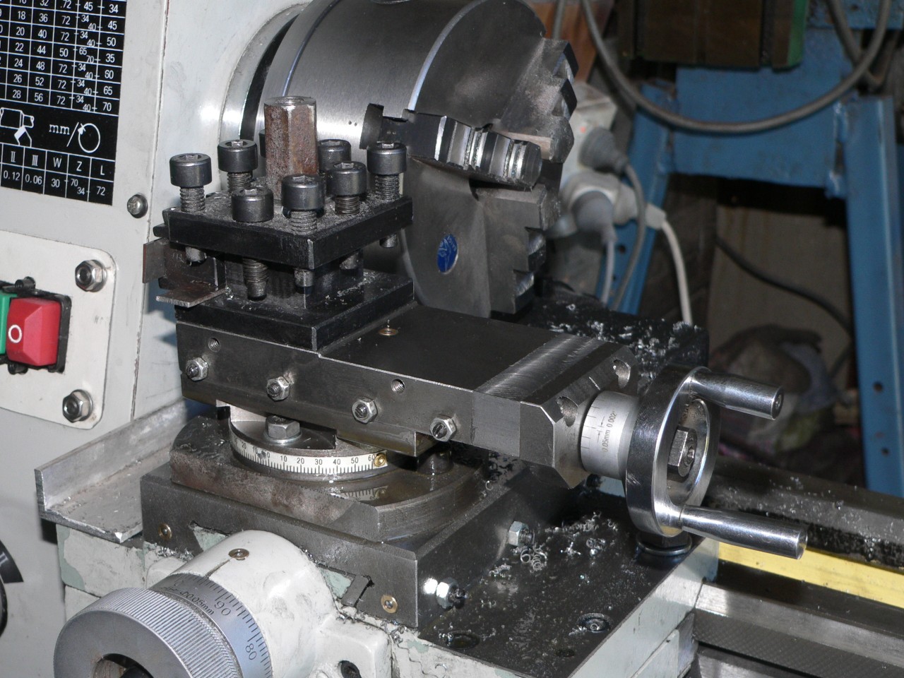
Here is the top slide in its mid position. For best results when not too close to the chuck I put tools in the right-hand side of the turret, tighten the gib screws right up, and use carriage auto feed. This should provide the best support for the tool.
The second photo shows the feedscrew hole (11mm) with the guide slightly protruding. The guide is affixed to the feedscrew and the outside edge is directly under the left edge of the top slide body. The Allen bolt lives in the recess at the end of the guide.
The top slide is tighter and smoother than before. It still binds a bit when turning the handle so it's not perfect. I might have bent the feedscrew slightly while cutting the thread.
Tool support
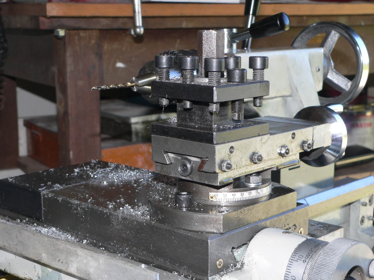
The top slide still seems to bend and affect the cutting quality. As an experiment I made a support for the tool. The tool bit must extend about 50mm from the tool holder. The support is just a bolt with a long nut that has a channel in the top. I set the tool slightly low and tighten the support by hand pushing the tip up to the correct height. Cutting sounds cleaner and the finish is noticeably better. Of course this arrangement can only be used for parallel turning and it does mean the top slide is jammed. What I need now is a similar support for the parting off bit.
Rob has a proper replacement toolpost. See his page for details and his comments on this upgrade. An impressive effort.
Parting tool holder

Many people have problems with parting off and I'm certainly in this group. Both my holders mount in the 4-way toolpost and the offset towards the chuck means the tool twists anti-clockwise when it grabs. Also the tool dips towards the work when it grabs. This normally either stalls the lathe or breaks the tool. So, parting was a high-stress disaster. But, things can be improved.
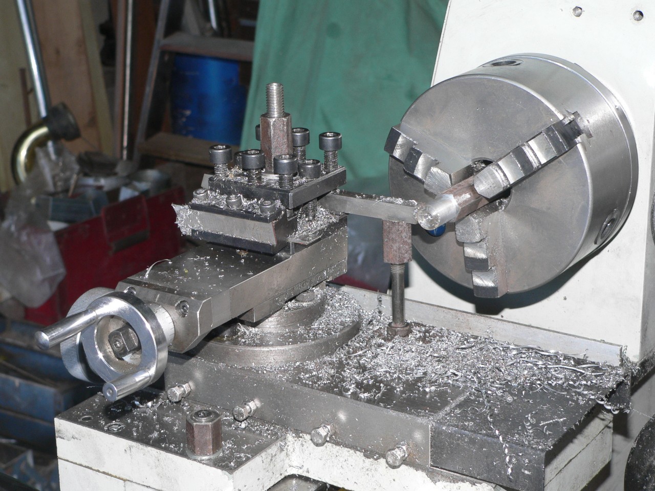
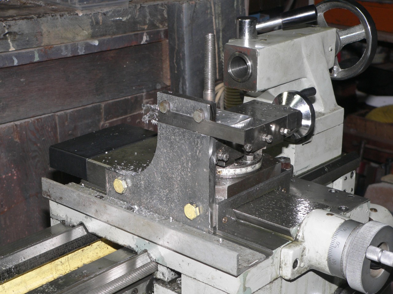
I made a holder from 10mm plate. This is mounted vertically and bolted to the chuck side of the cross slide. It has a 1/2" horizontal channel and the top of this channel is at centre height. So, the tool is automatically at centre height and perpendicular to the spindle axis. All I have to do is adjust the overhang. This holder works very well because the force is transmitted directly to the carriage.
The extra improvement here is to disengage the cross slide feedscrew and use a lever to push the cross slide. I added a stop at the front of the carriage and use a spacer block and long (about 700mm) lever which pushes the toolholder and therefore the tool into the job. This works a treat and I push with one hand and have a hand free to squirt coolant on the job. Soluble oil really helps here.
Next : Summary