| Introduction | Modifications |
Contents |
To totally void any warranty and also the resale value of the lathe I have made some changes. This page lists the minor changes; the next page contains the more involved changes.
- Top slide mounting holes
- Drive belt adjustment
- Better gear positioning
- Drive belt alignment
- Front panel switches
- Tailstock cam lock arm and holding nut
- Top slide feedscrew
- Carriage feedwheel
- Carriage guides
- Tumbler neutral stop
- Carriage lock
- Crank handle
Top slide mounting holes

The cross slide has two threaded holes for mounting the top slide. The holes are 81.2mm apart but the holes in the top slide base are 80mm apart. The bolts had been forced into place but they were skewed and the threads in the base were damaged. I drilled the blind holes so they are through holes and re-tapped them. Also I elongated the holes in the top slide to match the 81.2mm spacing. One of the bolts hit the top of a gib strip so I filed a recess in the gib strip.
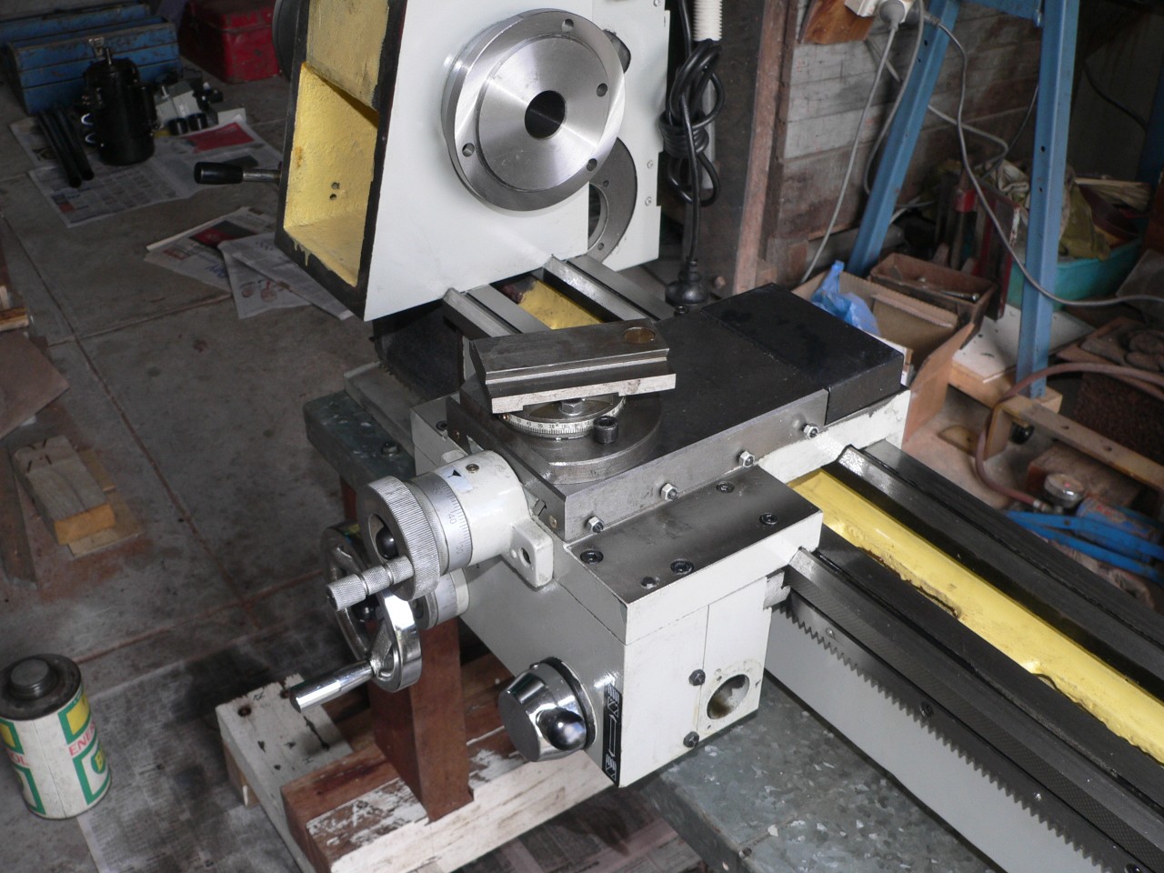
Here is the top slide base with one of the mounting bolts in the foreground. The extra 0.6mm clearance means that the Allen bolts don't hit the angle scale or the rivets at each end. The T-bolt heads have been cleaned so they don't catch when rotating the top slide. The top-slide base has a circular T-slot which is an impressive bit of machining.
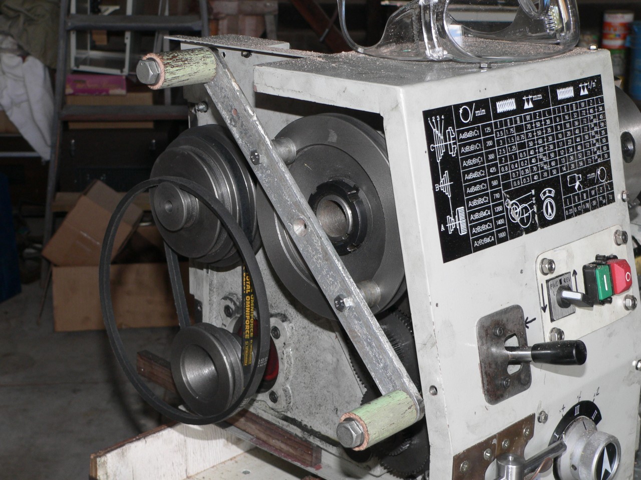
Drive belt adjustment
The slot for the pulley adjustment is too small for the full range. Here the slot has been enlarged to allow more adjustment. This didn't work as planned because the washer that covers this slot isn't large enough to always bridge the gap. I now use a small washer that never hits either side of the slot. This makes belt tensioning easier because the intermediate pulley can be positioned and fixed to set the lower belt tension only and the upper belt is tensioned by the weight of the motor and its frame. In the standard setup tightening the pulley shaft nut locks the motor frame and the tension of both belts must be right when this is done.
This arrangement over-tensioned the upper belt due to the weight of the motor so I now have a wedge under the motor frame to support it. Both belts are now just tight enough to transmit the drive. There is no vibration and the belts should last much longer with their new relaxed lifestyle. What I would really like here is to have the motor fixed and the intermediate pulley pulled up and back by an arm. Then the movement would tension both belts and it would be easier to release the tension for when the lathe is closed down or for changing the spindle speed or to turn the spindle by hand.
Better gear positioning
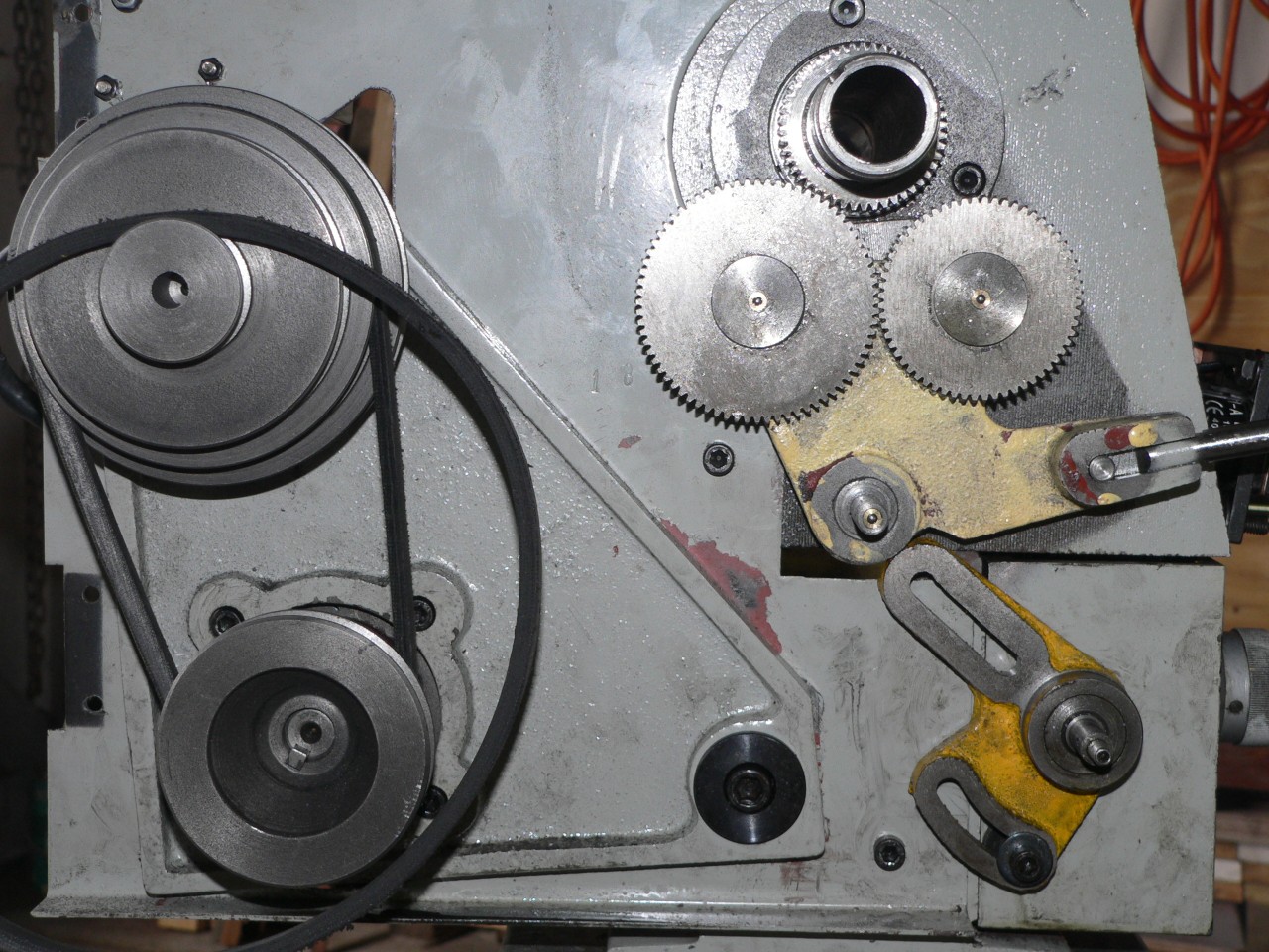
The tumbler frame here has been trimmed underneath to allow the gear positioning frame to be lifted a little higher to the limit of its range as set by its locating slot at the bottom. This allows extra combinations of gears so the lathe can produce 5mm pitch threads. It would be nice to have an indent for the neutral position of the reversing lever but this can't be done as the two holes for forward and reverse are too close together to have a hole in between. The gear positioning frame needed machining as the slots and back face were badly out of line. The locating Allen bolt in the bottom slot can be removed to fill the gearbox or check the level when filling via the oil hole on the outside. The user manual mentions filling the gearbox but the documentation doesn't match the reality on my lathe.
Drive belt alignment
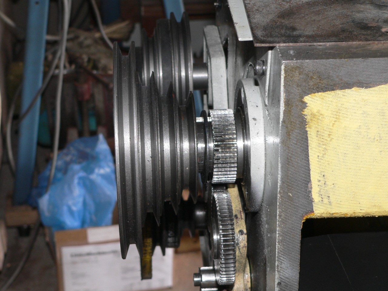
The pulleys don't line up correctly. Perhaps this is a very smart bit of engineering that allows for the distortion that occurs due to belt tension but I doubt it. The distance between the Vees on the pulleys isn't consistent so alignment is a fudge at best. I machined a 3mm thick washer and fitted it behind the pulley on the spindle. This improves belt alignment especially when using the slow range settings. The spindle pulley hasn't been pushed home in this picture so you can see the new washer between the pulley and the gear.
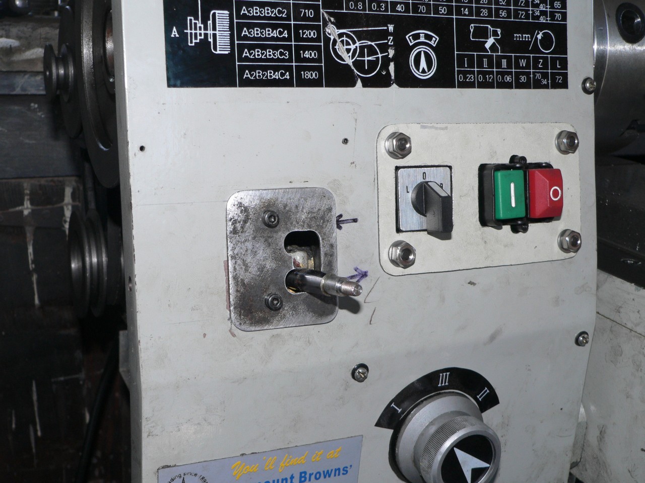
Front panel switches
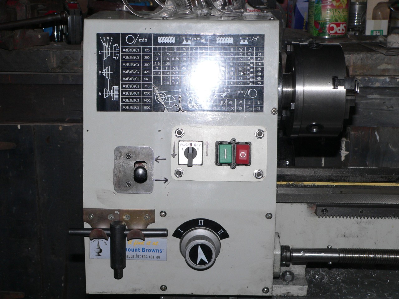
The switch assembly has been modified so the faceplate lives behind the cover rather than in front. This means I can now remove the front cover without disconnecting the cables at the back. Also the assembly is upside-down so the direction switch is now on the left. The old faceplate now has bolts facing forward and through the new faceplate I made. The stop/go relay switch wiring surprised me as the relay doesn't release when the forward/off/reverse switch is switched to off. I expected the run procedure would be to set the direction switch to forward and then use the stop/go buttons to control the motor. But this was a silly presumption considering that the ON button is not readily accessible with the standard setup. So I used the direction switch to control the motor and only press the stop button when leaving the lathe. This works well but I suspect that contact arcing will cause premature failure of the 4-pole direction switch.
Recently I had a bit of a problem when cutting threads because I would change the direction switch to the right (forward) but the carriage goes to the left. To reverse to do another pass I had to change the direction switch to the left but since I wanted the carriage to go to the right I sometimes mistakenly changed the direction switch to the right. This setup didn't seem very intuitive to me.
Now I have altered the wiring so the switch is left for forward (anti-clockwise) and right for backwards. The labelling on the switch was L O R and is now FWD REV. Also I have gone back to leaving the direction switch in the FWD position and using the stop/go buttons to control the motor. This seems more "standard" to me and avoids a problem where the lathe keeps running if the direction switch is moved past off to the other direction (the direction factor only applies when the starting winding is connected and this only happens when the motor is stopped or very close to it).
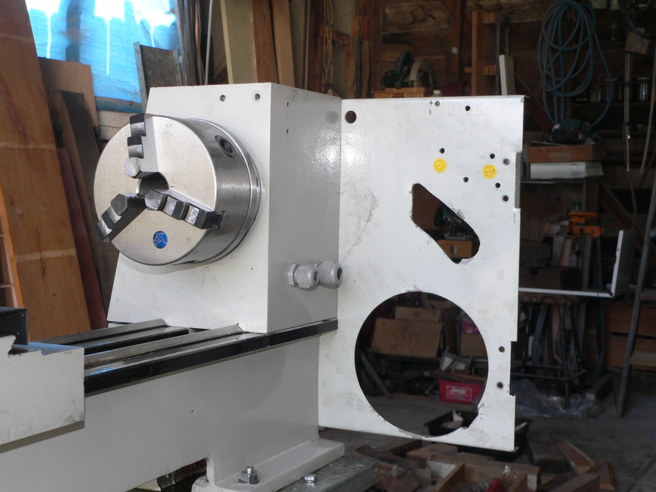
Tailstock cam lock arm and holding nut
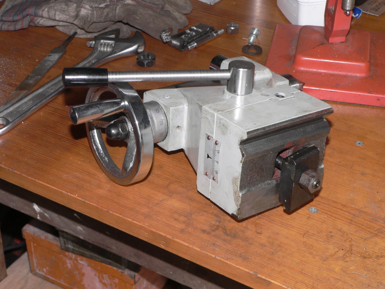
The tailstock now has a longer cam arm. The original is the 70mm arm that is used in a few places on the lathe. The 150mm replacement is far better for the cam arm. Notice the banding on the new arm. This is a problem with my lathe when using auto-feed. I replaced the nut under the tailstock with a nyloc nut but this didn't work because the thread on the clamp rod is a bit undersize and was starting to strip. The current replacement is a homemade 10mm nut and the long thread means it can stand the force when the tailstock is clamped. The thread has been coated with epoxy glue so it is a tight fit and doesn't rattle loose.
Top slide feedscrew

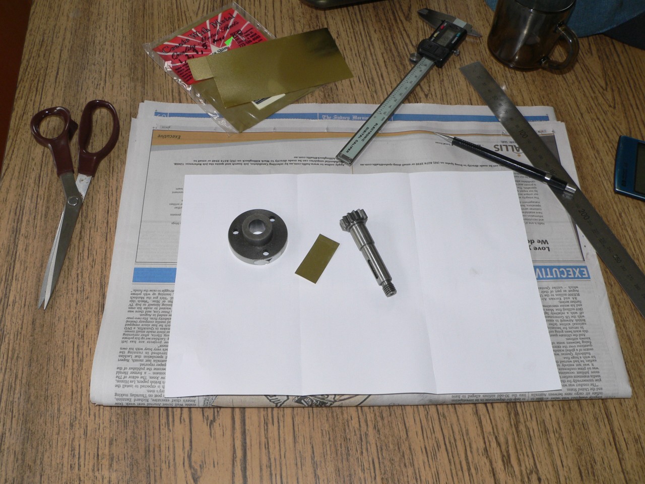
The top slide feedscrew was catching because the journal was off centre. I tried skimming it to reduce the high half but the resultant slop caused the shaft to bind when I pushed on the handle. I had to reduce it to 9.22mm (was 10mm) and then fit a 0.015" brass sleeve to bring it up to 10mm. Only the portion that fits in the housing was reduced. The top slide is much smoother now but the handle is off-centre as I didn't machine that portion of the shaft.
The feedscrew is held here in a sleeve made from brass tube with a split down it. I managed to machine the journal without marking the thread but the cuts had to be very light (about 0.002") as the rod was only lightly held in the chuck. The top slide has been locked by tightening the gib screws and longitudinal feed was supplied by the carriage auto feed. The graduations on the carriage handwheel (each revolution is meant to be 20mm but is actually 19.91mm) are a very handy feature on this lathe. 23 revolutions turns out to be 458mm (should be 460mm) so it is close enough for many jobs.
I have now rebuilt the top slide and the section in the next page shows the result.
Carriage feedwheel
The carriage feedwheel had an annoying wobble due to a sloppy bearing. The one bearing for this shaft is 20mm long. The shaft diameter is 13.95 and the hole in the boss was about 14.05mm. I bored the hole to 14.12 and made a 20mm by 44mm shim of 0.003" brass and rolled it so it fits in the hole. Now the feedwheel is nice and tight and smooth. I used the top slide for longitudinal travel when boring the hole and although it was set to 0° the hole diameter varies from 14.12 at one end to 14.16 at the other. This is about .05° out so the degree scale is much better than expected.
Follow up : This bearing developed a bit of play so I bored the hole to 15mm and fitted a brass bush as a replacement. It is difficult to eliminate play here due to the short length of the bearing. The new bearing is smoother than the shim bearing. Both replacements here are much better than the original setup.
Carriage guides
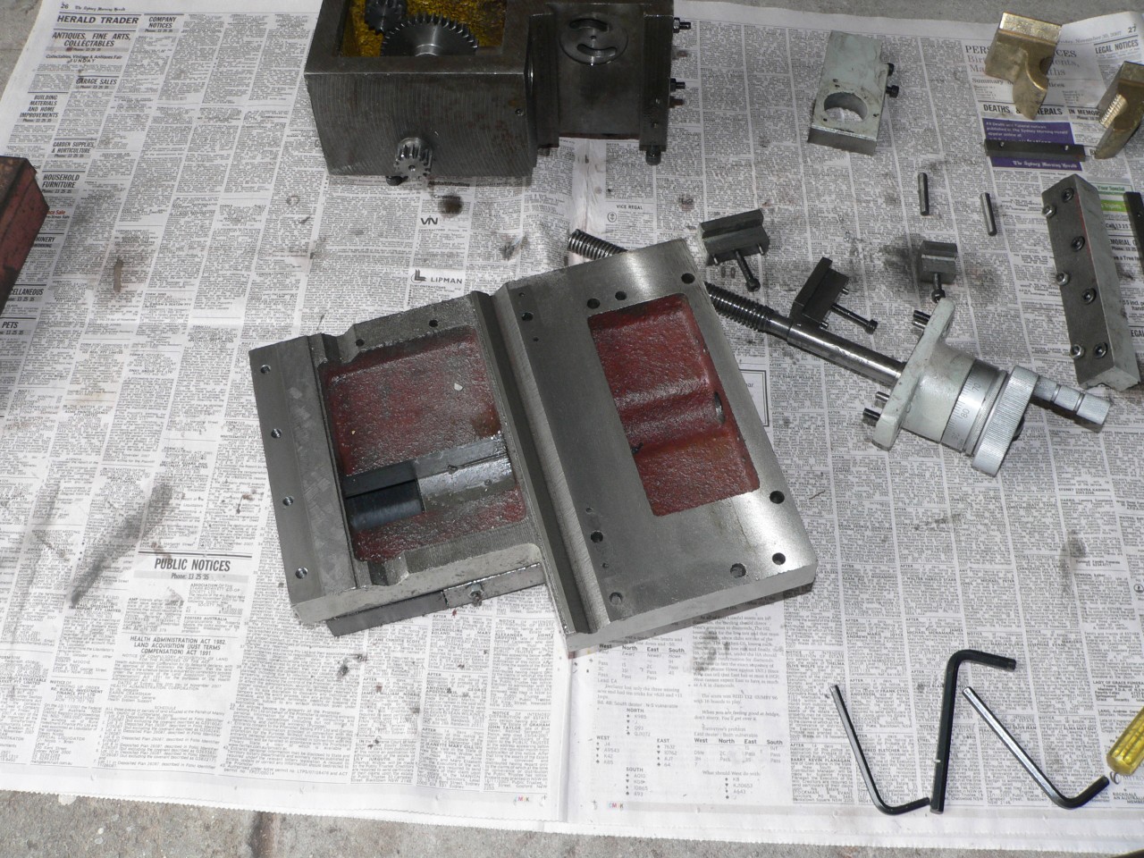
The machining on the carriage guides for the bed seems terrible. However, the carriage does run true and there is no rock. I polished the highs but the guides were still rough. Rather than risk machining them and doing permanent damage I made slippers from 0.005" brass shim and glued these to the carriage.

Here is the saddle with the brass slippers fitted. It is a bit hard to see as the light adds a yellow touch to the steel. The carriage now glides along the bed and feels great. Time will tell if this is an improvement and how long it lasts.
The 0.005" shims change the clearance of the anti-lift guides. The back guide has a gib and still fits correctly. The two front guides are fixed and they jammed the saddle when tightened. Ordinarily I would fit a shim between the guides and the saddle but since the machining on these guides was terrible I decided to mill a few thou off the bearing face instead.
Using the vice here allowed me to remove the guide for testing and then re-clamp it for more machining without having to check the setup each time. The front (moveable) jaw of the vice is parallel to the X-axis so the machined bearing face will be parallel to the meeting face.
Tumbler neutral stop
The tumbler lever has stops for forward and reverse but none for the neutral (no feed) position. The two holes for the existing stops are too close together for drilling an intermediate hole. Rather than modifying the existing mechanism (which would require drilling holes in the headstock), I cut out a plate and bolted it to the front panel. The slot in the plate has a big recess at the top and bottom and a smaller recess in between for the neutral stop. The width of this middle stop is restricted by the distance (5mm) between the big recesses. The depth is less than the other recesses as the lever will not return much further to the left in this middle position as the standard locking pin (behind the cover) is not over either of the two standard holes in the headstock. This is not a failsafe lock as the lever can be pushed off the middle recess. A more definite lock using this arrangement would require machining a groove partway through both the top and bottom of the tumbler lever and then making a new plate with suitable recesses. The good thing about this fix is that it can be done without modifying or removing the tumbler lever. Removing the tumbler level entails removing the pulley from the spindle and you might require a new locking tab when refitting the pulley.
Notice how my poor lathe is looking like a tired old piece of junk due to all my meddling here. It is only about one month old. Imagine if I had bought a new car instead.
Carriage lock
Rob mentions his improvement to the carriage lock in his review and I had the same problem where the lock is a sloppy fit. Also, I found the Allen bolt annoying because the socket fills with shavings and must be cleaned before the Allen key will fit.
I fitted a piece of 1/16" steel behind the lock to stop it twisting and reduce the skewing. I replaced the M5 Allen bolt with a hex head version but it bent under load. To get the strength of an Allen bolt I drilled a head made from 5/8" hex steel and pressed in an M6 Allen bolt. This works well for me as I have a 5/8" toolpost nut so I can use the same spanner for both. The carriage lock bolt can be tightened by hand and this provides enough resistance for light jobs. To get the M6 bolt to fit here I had to elongate the 6mm hole in the saddle so this job was harder than expected.
Crank handle
Cutting threads at 125 RPM can be a stressful hassle particularly when the lathe doesn't stop in time and the tool crashes into a shoulder or the end of the partially made thread. A crank handle to facilitate hand turning is the obvious answer. There isn't much meat near the outside of the pulley but there is just enough to drill and tap holes for M6 bolts.
The pitch circle for the two holes is 117mm and I have 20mm spacers so the bar with the handles will clear the front/top cover. I was tempted to use studs instead of bolts but this is a bit risky since I don't have the door for the belt drive area. If I make a replacement bar I will use 50x6 bar and have a 26mm hole in the centre as per the spindle. Fixing the spacers to the bar would be a good idea so they don't get lost when the bar is not in use.
In the picture it looks like the bar will hit the front cover. This is just a case of my camera creating optical illusions. The bar has two handles to make it easier to use when I am in front of the lathe.
Next : More changes