| Introduction | Lathe Details |
Contents |
Here are some purchase and technical details that might be of interest. There isn't much choice with purchase as Paramounts is the only source I know. Most of the specifications agree with the advertised specs. The extra specs here are things I wanted to know when looking for a lathe.
- Purchase info
- Verified specifications
- Top slide
- Cross slide
- Carriage
- Tailstock
- Gear train
- Main bearings
- Spindle
Purchase info
I bought the lathe from Paramount Browns in Adelaide. Their product name is BLC-1016. It cost me $1099 plus $140 for transport to Sydney and delivery using a tail-lift truck. The lathe comes with a 3-jaw chuck, 2 dead centres, a travelling steady, and a minimal manual and tool kit.
Verified specifications
| Detail | value | comment | |
|---|---|---|---|
| Between centres | 440 | mm | max carriage travel is 434mm |
| Swing over bed | 250 | mm | |
| Swing over cross slide | 150 | mm | |
| Cross slide travel | 125 | mm | |
| Top slide travel | 70 | mm | about 60mm usable travel |
| Tailstock travel | 40 | mm | 45mm at a pinch |
| Tailstock feedscrew | 10 | TPI | this is 0.1" not 2.5mm, dial marks are 0.001" (not 0.025mm) |
| Cross slide feedscrew | 10 | TPI | this is 0.1" not 2.5mm, dial marks are 0.001" (not 0.002" / 0.05mm) |
| Top slide feedscrew | 1.25 | mm | M10 x 1.25 V-thread not ACME profile |
| Top slide rotate | 360 | ° | Marks from -60° to +60° |
| Imperial pitches | 21 | 8, 9, 10, 11, 12, 13, 14, 16, 18, 20, 22, 24, 26, 28, 32, 36, 40, 44, 48, 52, 56 TPI | |
| Metric pitches | 17 | .2, .3, .35, .4, .5, .6, .7, .75, .8, 1, 1.25, 1.5, 1.75, 2, 2.5, 3, 3.5 mm | |
Top slide
The top slide has a handle with a resettable dial. The dial has 25 graduations of 0.05mm so each revolution is 1.25mm. The fastening nut for the handle has a grub screw for backlash adjustment. The top slide can rotate 360° and the dial is graduated from -60° to +60°. For accurate work I would use a protractor rather than trust the markings because the scale is affixed not imprinted.
The turret will take bits up to 1/2" sq. I have replaced the clamp with a long M10 nut as the handle of the clamp was always getting in the way.
The 1.25mm thread pitch makes it harder to advance a specified distance. A 1mm or 2mm pitch would make calculations easier here. The 0.05mm graduations are a bit coarse. As the cross slide feedscrew is imperial (10 TPI) I would much rather have a 10 or 20 TPI feedscrew here and a dial with 100 or 50 graduations.
The holes in the base are 80mm apart which doesn't match the spacing in the cross slide which is 81.2mm. Elongating the holes in the top slide base solves the problem. Perhaps the cross slide spacing is imperial (3 3/16" or 3 1/4") because this spacing mismatch is not unique to my machine. The slightly wider spacing (81.2mm) is better because the Allen bolts just clear the degree scale whereas with the 80mm spacing they will just touch and end up scratching the scale.
Cross slide
The cross slide is a solid affair with a guard at the back to stop swarf getting on the slideways. The travel is 125mm which restricts the maximum diameter that may be faced to about 200mm.
The cross slide has a 10 TPI ACME thread. The dial has 100 graduations which are marked as 0.05mm or 0.002" (at least one must be wrong). In fact the graduations are 0.001" (nearly 0.025mm). Perhaps the marking refers to diameter rather than radius. The threaded shaft has ball-bearing thrust races which make it noticeably smoother than the top slide.
The register mark for the feedwheel is a stick-on label rather than an engraved line. The same label is used for the carriage and the tailstock. The label is good because the arrow is easier to see than a thin line. However, with the help of some oil and diesel all my labels fell off fairly quickly. So, a good idea but it doesn't quite live up to expectations.
Carriage
The saddle is well made except for the V-groove and the pad where it runs on the bed. For some reason the machining here is terrible and I can't see any value in having such rough surfaces. The anti-lift guide at the back has a gib and screws to minimise play. The front anti-lift guides have no adjustment or shims. The third front guide is actually the carriage lock.
The apron has the manual feed mechanism and the half nuts for auto feed. The manual feed wheel is sloppy because the short bush is 14.05mm and the journal is 13.95mm. I suspect that both are wrong. The feed wheel has a resettable dial with 40 graduations of 0.5mm. The feed should be 20mm per revolution but is 19.91mm which is an error of less than 0.5%.
The half nuts have a gib to improve alignment. There is no adjustment to centre the nuts on the leadscrew. The apron has a leadscrew guide to restrict run-out at the half nuts. The guide is 20.40mm ID and the leadscrew is 20mm OD.
Tailstock

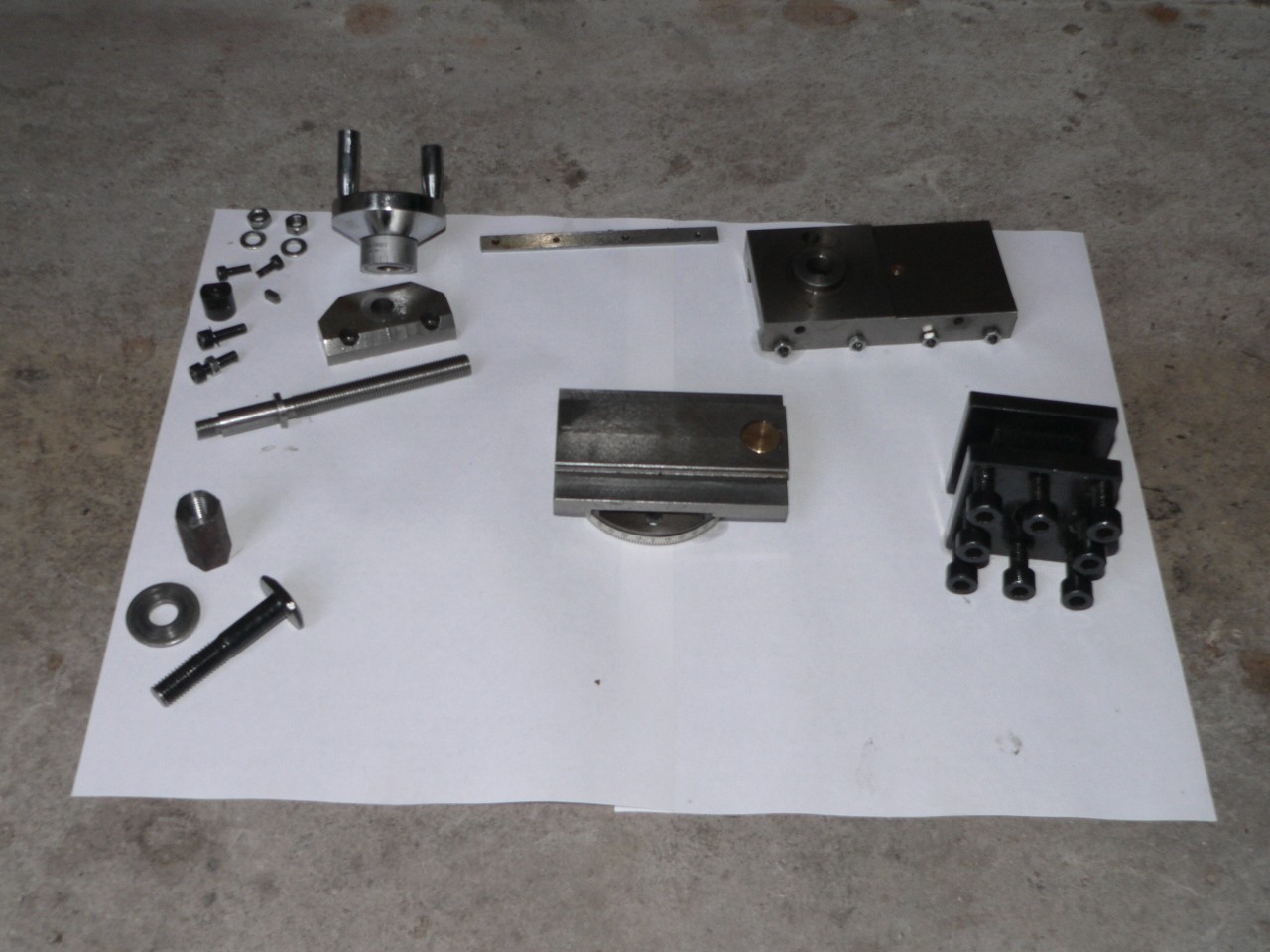
The tailstock is shown here slightly dismantled so you can see the lateral positioning arrangement and the cam lock. The meeting faces here were rough (surprise, surprise) and have now been polished. The locking plate and nut are in front of the base. There is no height or angle adjustment but my tailstock seems fine so this isn't a worry.
The lateral adjusting spigot has a circlip that holds the base and body together but they are only held firmly together by the cam lock. This might affect precision work if there is any play between the spigot and its hole in the base as the alignment could shift slightly. Maybe two bolts holding the base to the body are needed. Alternatively the spigot could be glued into the base (say Devcon) to ensure there is no play.
There is a metric depth scale on the barrel and the dial on the feedscrew is imperial. The tang must be cut off any 3MT fittings used here to avoid hitting the end of the barrel. The feedscrew will eject the fitting when retracted fully.
Gear train
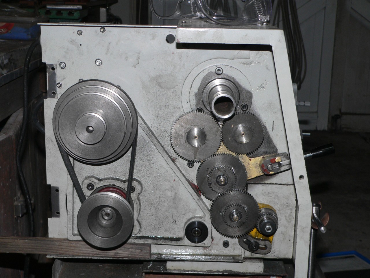
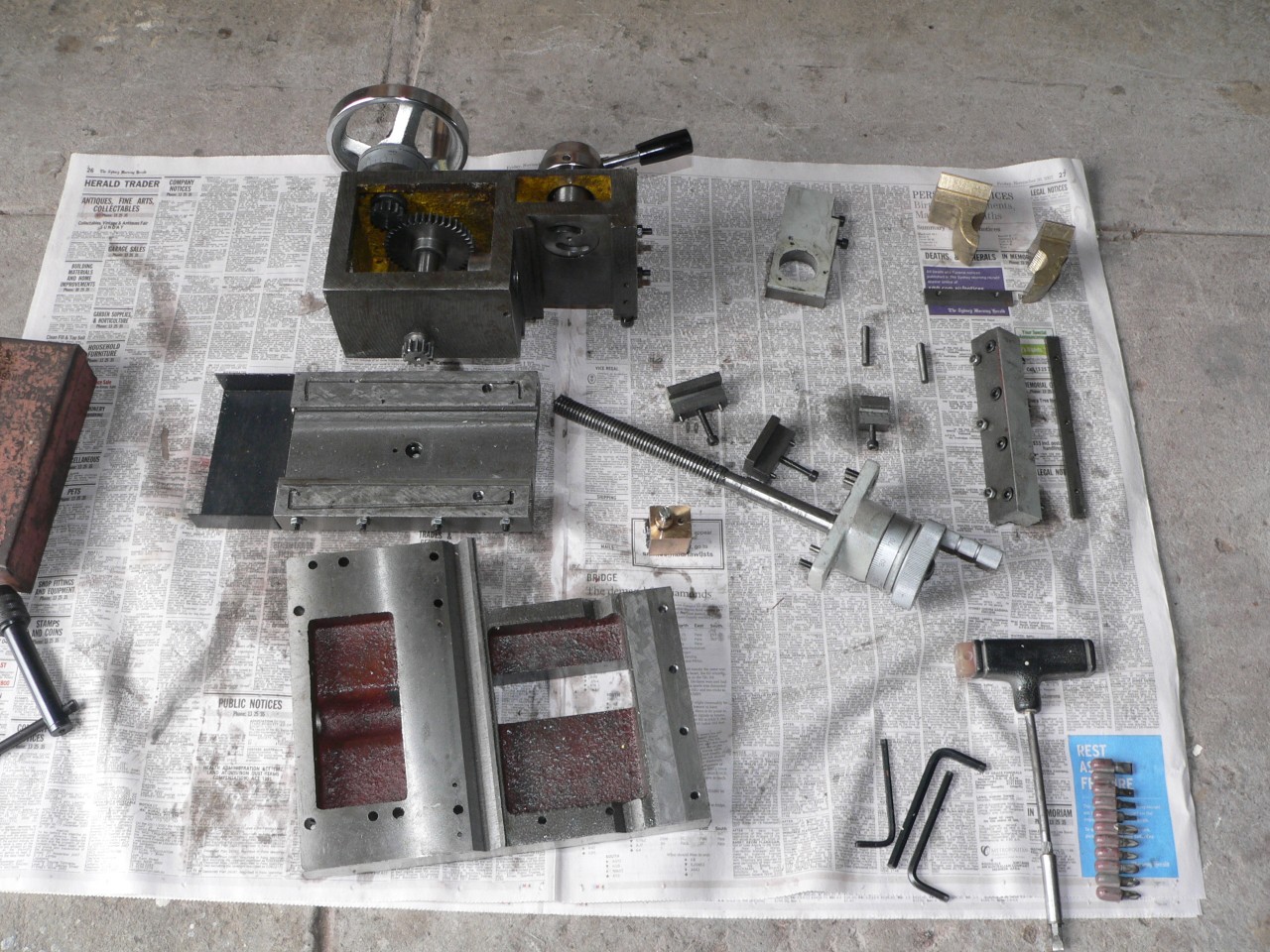
The gear train for thread pitches and fine feed has a tumbler reverse, changeable gears, and a three-speed gearbox. The spindle gear (missing in this image) is 48 teeth and the tumbler common gear is 72 teeth. The gearbox provides ratios of 3:16, 3:8, and 3:4. The leadscrew pitch is 3mm.
The pitch table on the lathe specifies 0.06mm, 0.12mm, and 0.23mm for the fine feed rates. The actual feed rates are 0.076mm, 0.15mm, and 0.30mm. This discrepancy was noted by a friend and I've verified it both by mathematics and testing. I guess the designer was having a bad hair day. This increase doesn't matter because the finest feed is too slow for most tasks anyway.
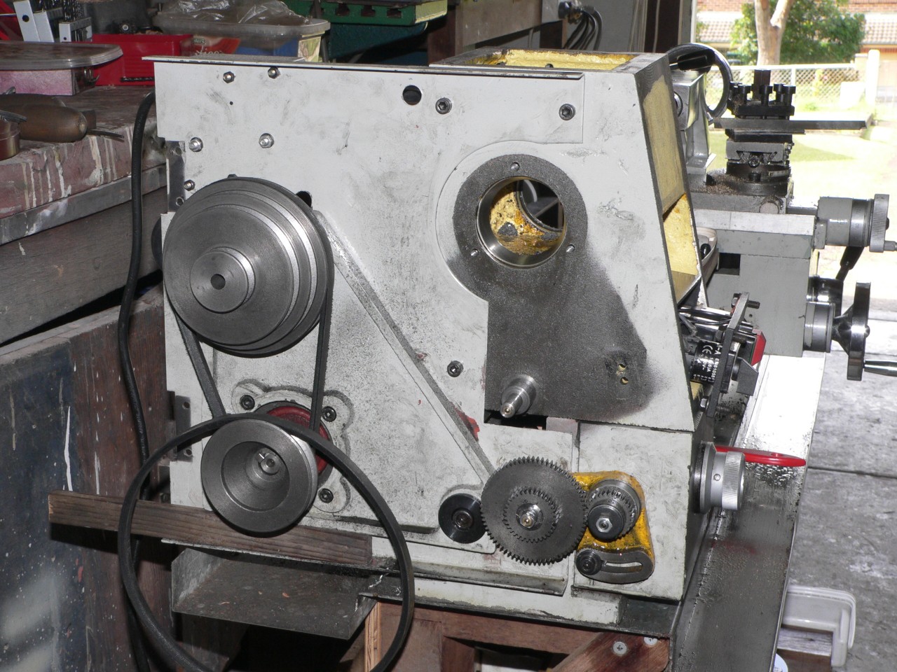
The wooden stick that you're not meant to notice is my wedge for adjusting the top belt tension. This is a "temporary fix" that works so well that I'm reluctant to replace it. To release the tension I lift the end of the stick. To set the tension I squeeze the belt and move the stick until it supports the motor frame.
Main bearings
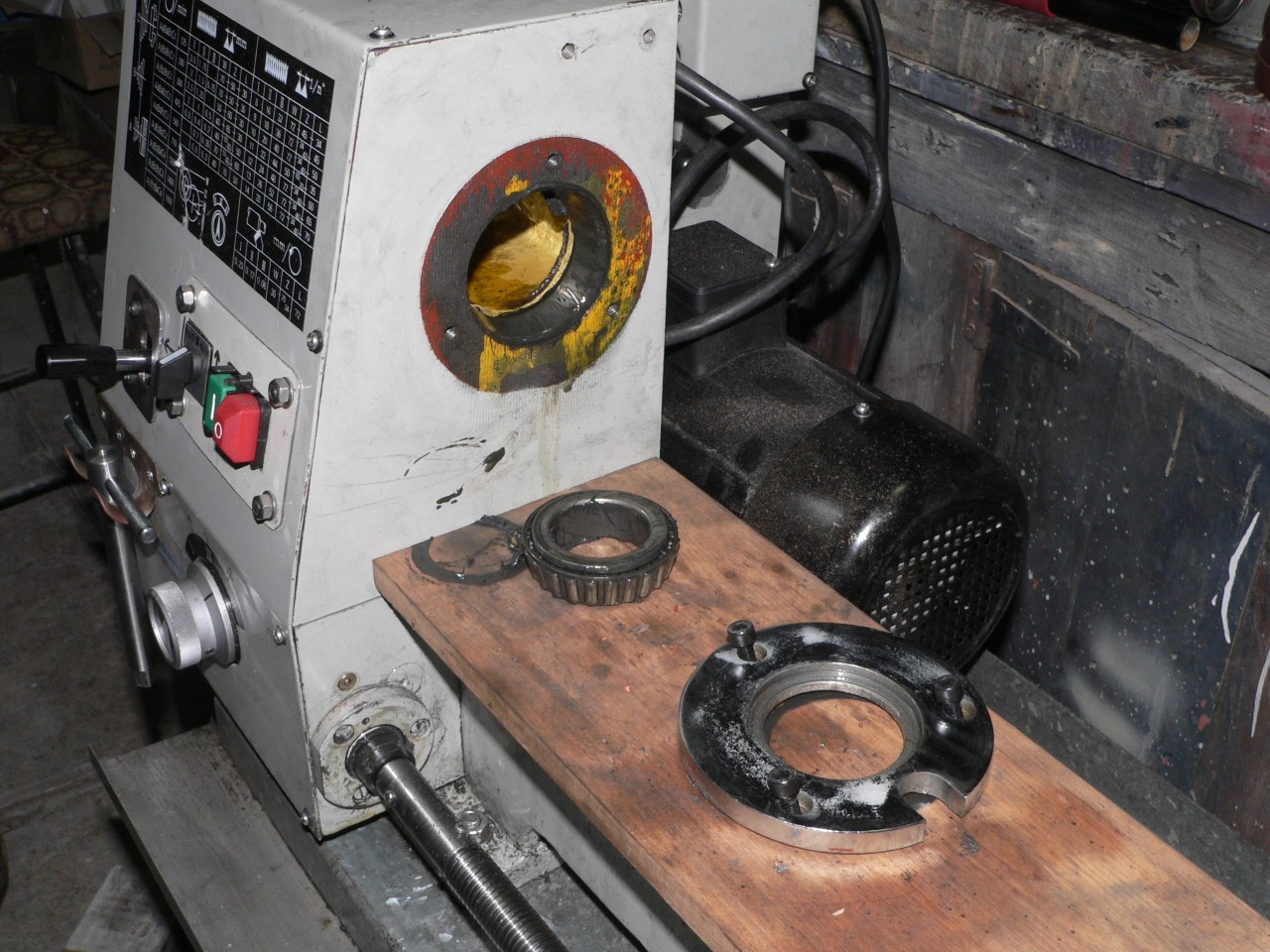
The spindle bearings are tapered roller bearings. The left bearing part code is 32007X (35mm bore, 62mm OD, 18mm wide) and the right bearing is 32008X (40mm bore, 68mm OD, 19mm wide). Each bearing has a lipped cap to keep out swarf. There are no oil seals. It is just possible to grease the bearings by removing the top panel but access is limited and it is difficult to pump grease between the rollers.
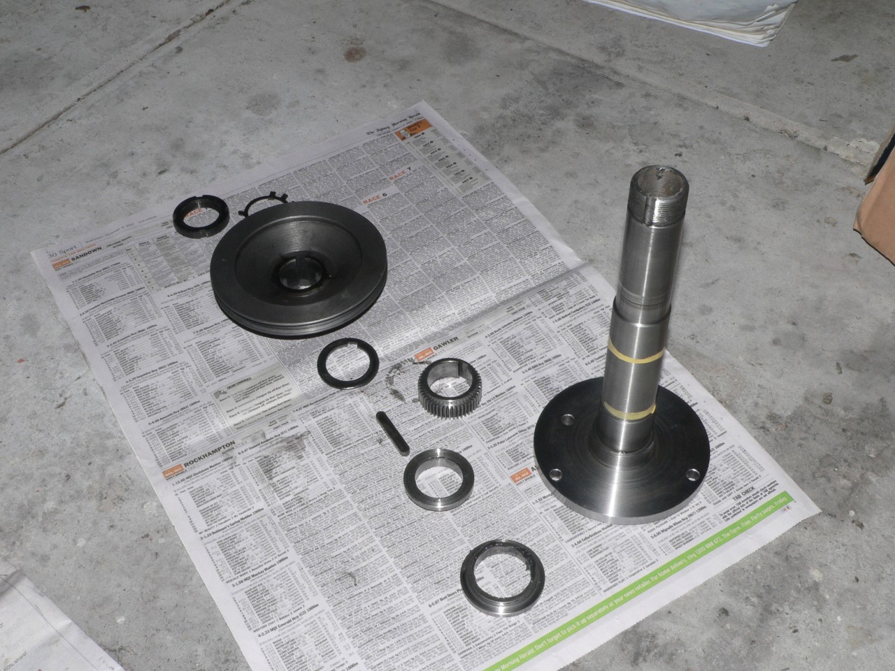
The bearing preload should be adjustable using the round nut that holds the pulley on the spindle. But on my lathe the left-hand bearing was a very tight fit on the spindle and no amount of gentle persuasion would move it. So I removed the spindle and then the bearing inner race and polished the bore until it was a tight fit but no longer a press fit. I didn't polish the journals on the spindle because they are exactly the correct size (35.00mm and 40.00mm). After reassembly I tightened the round nut until the spindle drag increased slightly.
When removing the spindle it is better if the right-hand bearing inner race stays on the spindle as less force is required so there is less chance of wrecking the headstock alignment. The chrome retaining plate behind the spindle flange has three Allen bolts and these can be undone via a hole in the spindle flange. Then the retaining plate, lipped cap, and inner race will stay on the spindle. At the left end the round nut, pulley, gear, and key must be removed. It should then be possible to remove the spindle from the right-hand side. If the left-hand bearing is a press fit on the spindle (as mine was) you will have to use extra force. Once the spindle is removed, removing the left-hand retaining plate (3 Allen bolts) will provide access to the left-hand inner race.
Spindle
The spindle has a 132mm flange with a 100mm locating boss and three bolt holes on a 115mm pitch circle. The bore is 26mm and the taper is MT4. The image below shows the dimensions and is a link to a PDF version of the drawing.
Next : Delivery