
Tiny Bum Truck
|
Tiny Bum Truck |
|
A friend wanted to steam and run a 5" gauge loco that hadn't run for 30 years. We did a hydrostatic test and then a steam test with the loco on blocks as we didn't have any track to run on. This all went well and the loco only required a few minor repairs and a carriage for the driver before we could take it for a real run.
The big problem with the loco is that the boiler was made before registration was introduced in 1968. Although the boiler seems okay the only way to get it approved is to dismantle the loco sufficiently so an inspector can ensure everything is adequate. So the project is in limbo because the owner doesn't want to pull the loco apart.
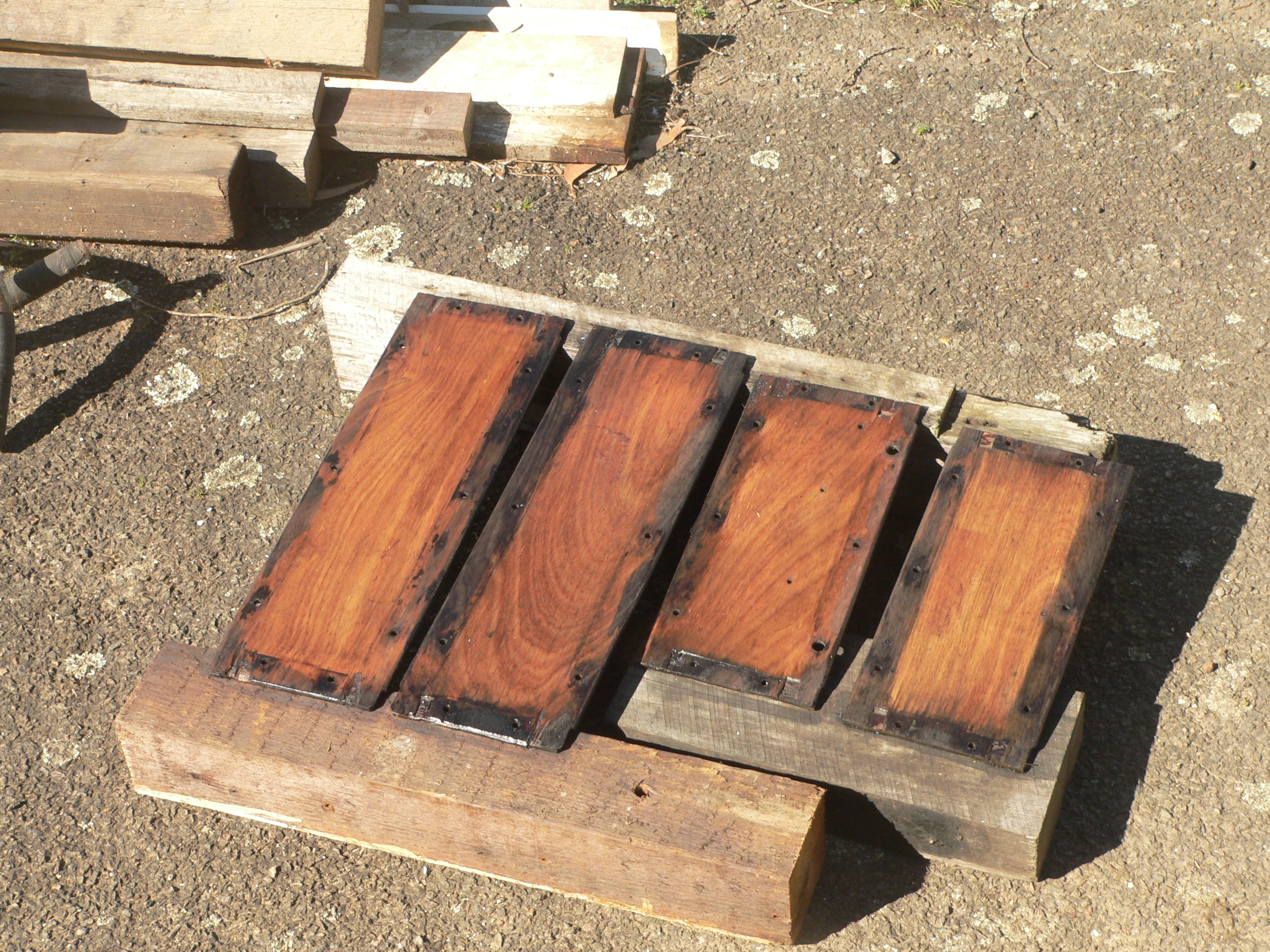
The need for a riding carriage (aka bum truck) got me looking through my collection of bits. I had a metal-framed box with wooden inserts that came from an old railway workshop. I also had a frame with two axles and wheelsets. Just enough for a quick and dirty carriage. So I started work on making a riding carriage.

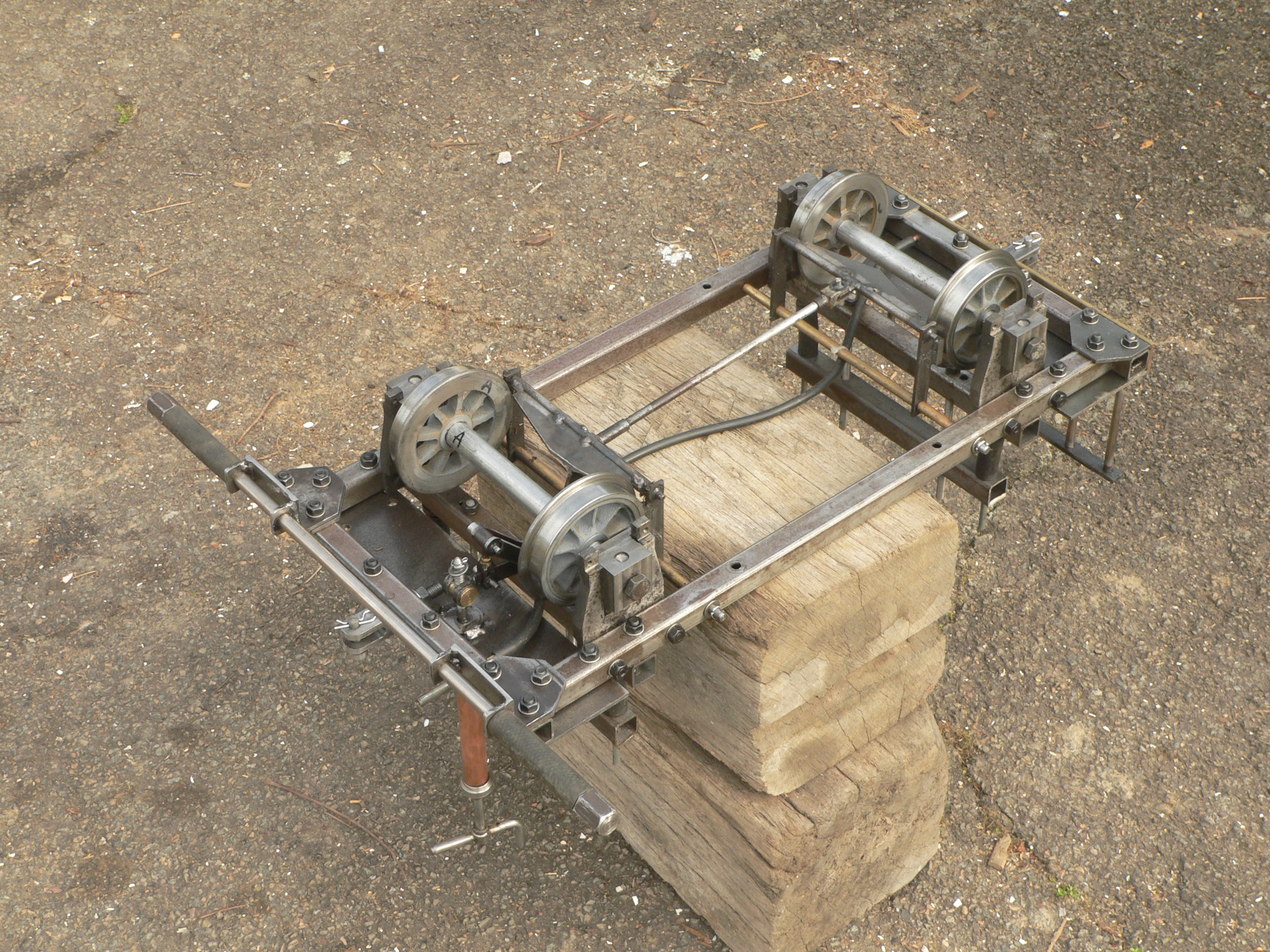
My starting point was this frame with horns and axleboxes with wheelsets. When I checked closely I found the frame was twisted (probably distortion due to welding), the horns had holes with broken taps, and the axleboxes were all different so nothing lined up. So much for the easy option of using this frame and just putting a seat on top.
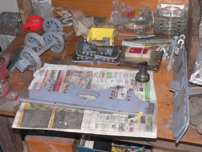
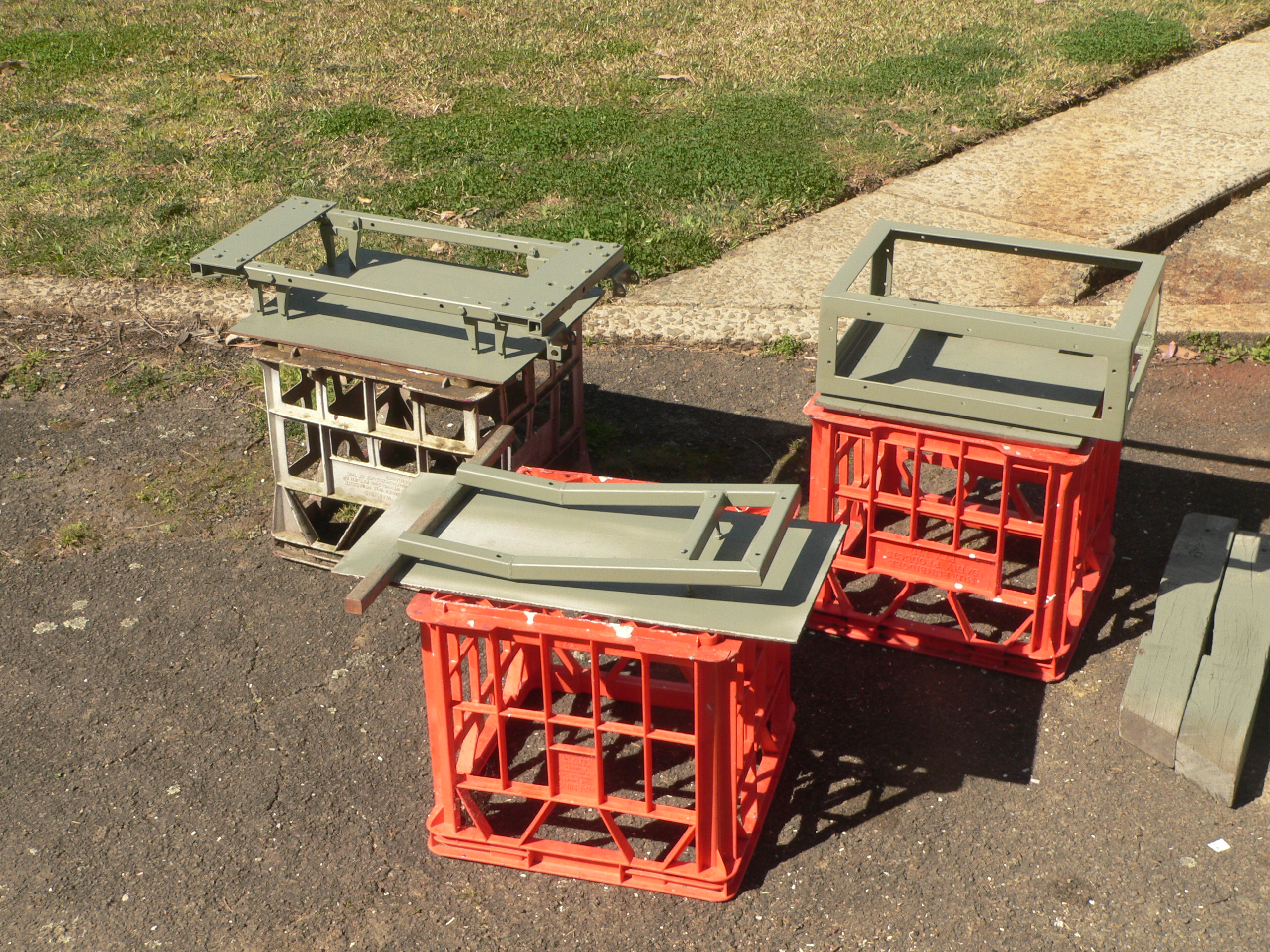
Most of the welds were pretty crummy so I cracked the frame apart and removed the horns. I realised that the frames are too short even for a tiny carriage and the horns are far too big and clunky.
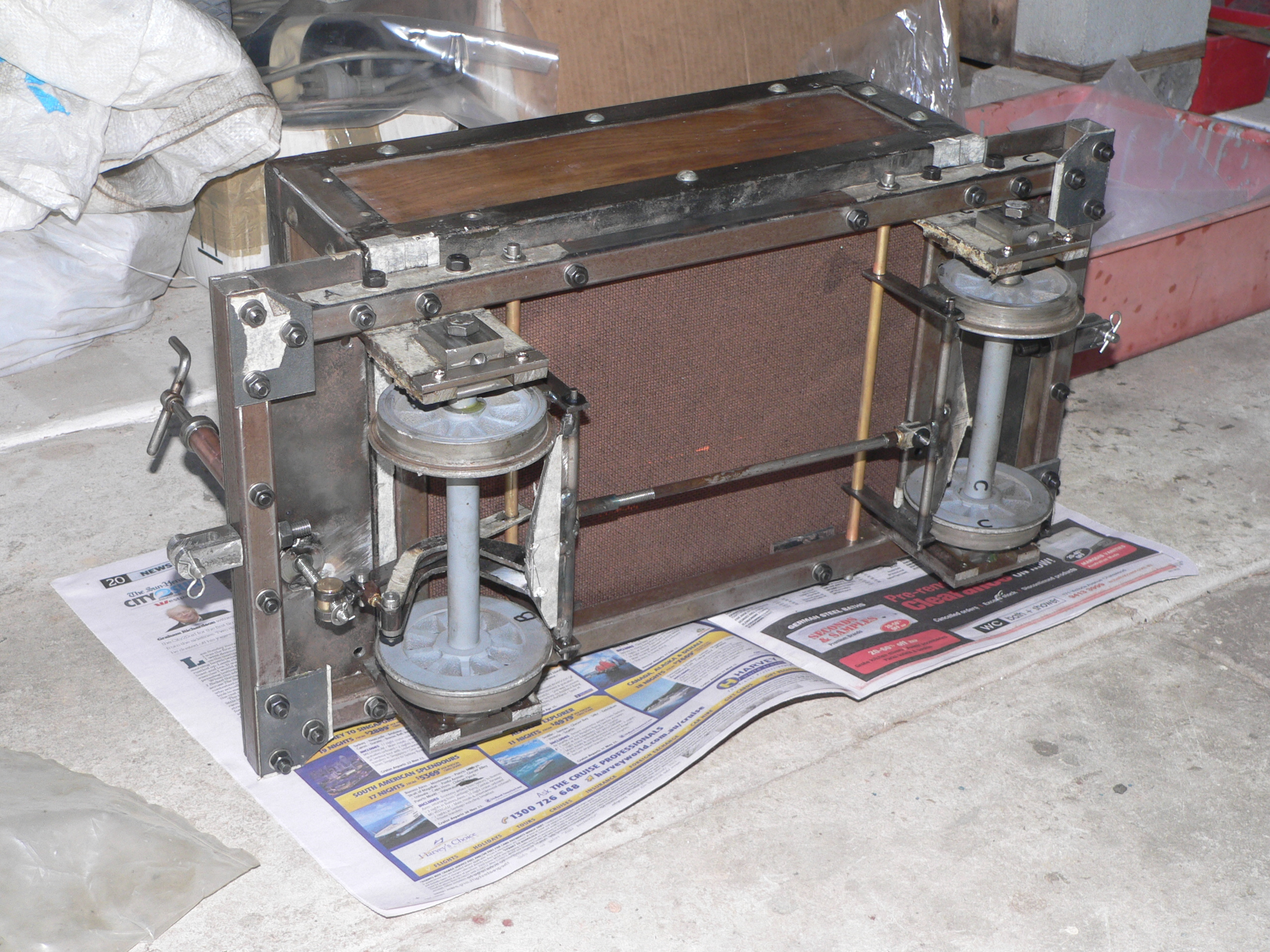
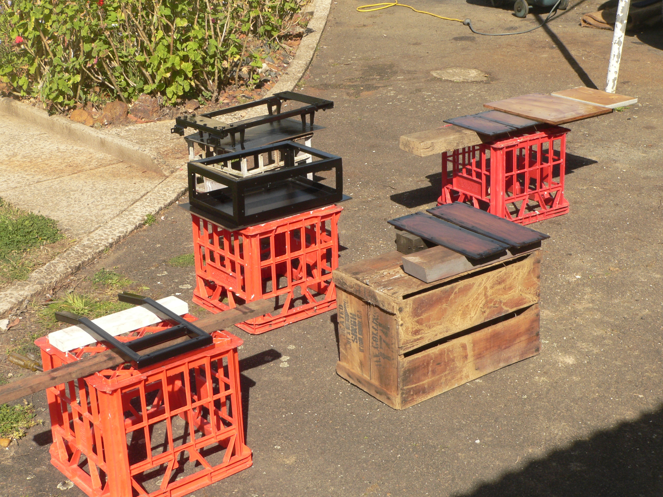
Here is the first attempt ready for a test. The metal-framed box has a seat and the frame is made from 3/4" square RHS that I had on-hand. The axlebox horns are made from 10mm steel and lots of elbow grease with a hacksaw. The axleboxes are from the original frame and have been machined so they're all identical. The ball races are at the inside edge of the axleboxes and the spring rods must bear above the bearings or the boxes will try to skew. There wasn't any room for springs under the frame so they're above the frame and inside the box. The side frames were going to be inside the horns but I ran into clearance problems with the wheels. The best solution to this design faux pas was to move the side frames outwards.

After a test run I've started on the brakes. In this picture only the hangers complete with shoes have been fitted. The photo does show the springs which are actually just lengths of rubber tube. The tube is rather lousy but does provide enough cushioning until I can find some suitable springs. The axlebox horns still aren't finished as the time and effort to hacksaw the outsides makes this a tedious and unpleasant task.
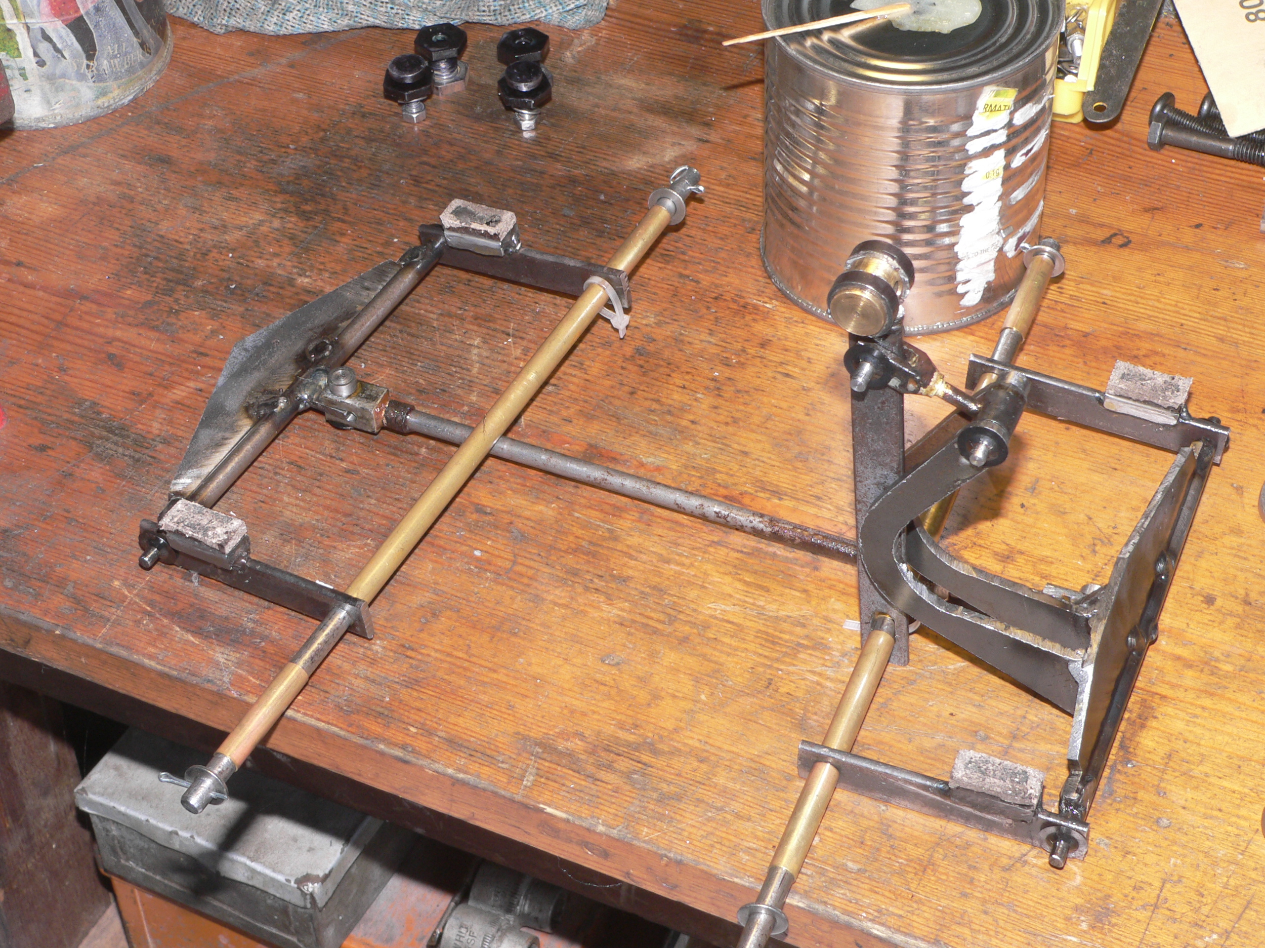
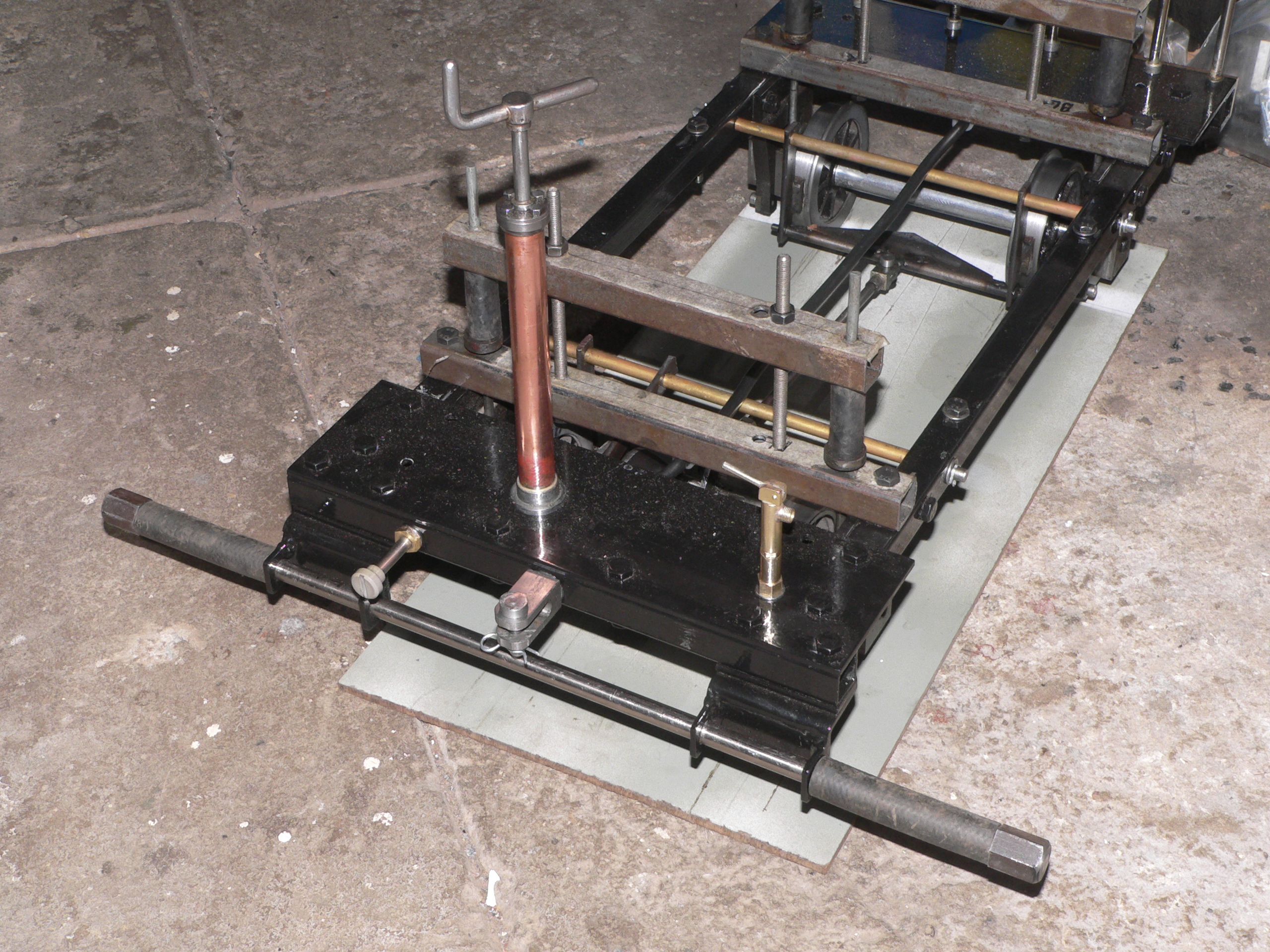
The brakes are now finished. The brakes can be screwed on (handbrake mode) or the handle can just be pulled up to apply the brakes. The brake shaft pulls the cranked arms to the crossbeam for the front brakes. This crossbeam has a crank that connects to the back axle crossbeam so equal pressure is applied to both axles. The crossbeams are braced to make them strong enough for the task.
During painting and disassembly (see below) I fitted brake pads to the steel shoes. The pads were made from a car drum brake shoe. I chiselled the lining off the backing plate and cut some of the broken pieces into suitable size pads. The linings are marked "may contain asbestos" so maybe cutting them using a hacksaw is not such a good idea. Previously I tried cutting disc brake pads but the material is far too hard and brittle.
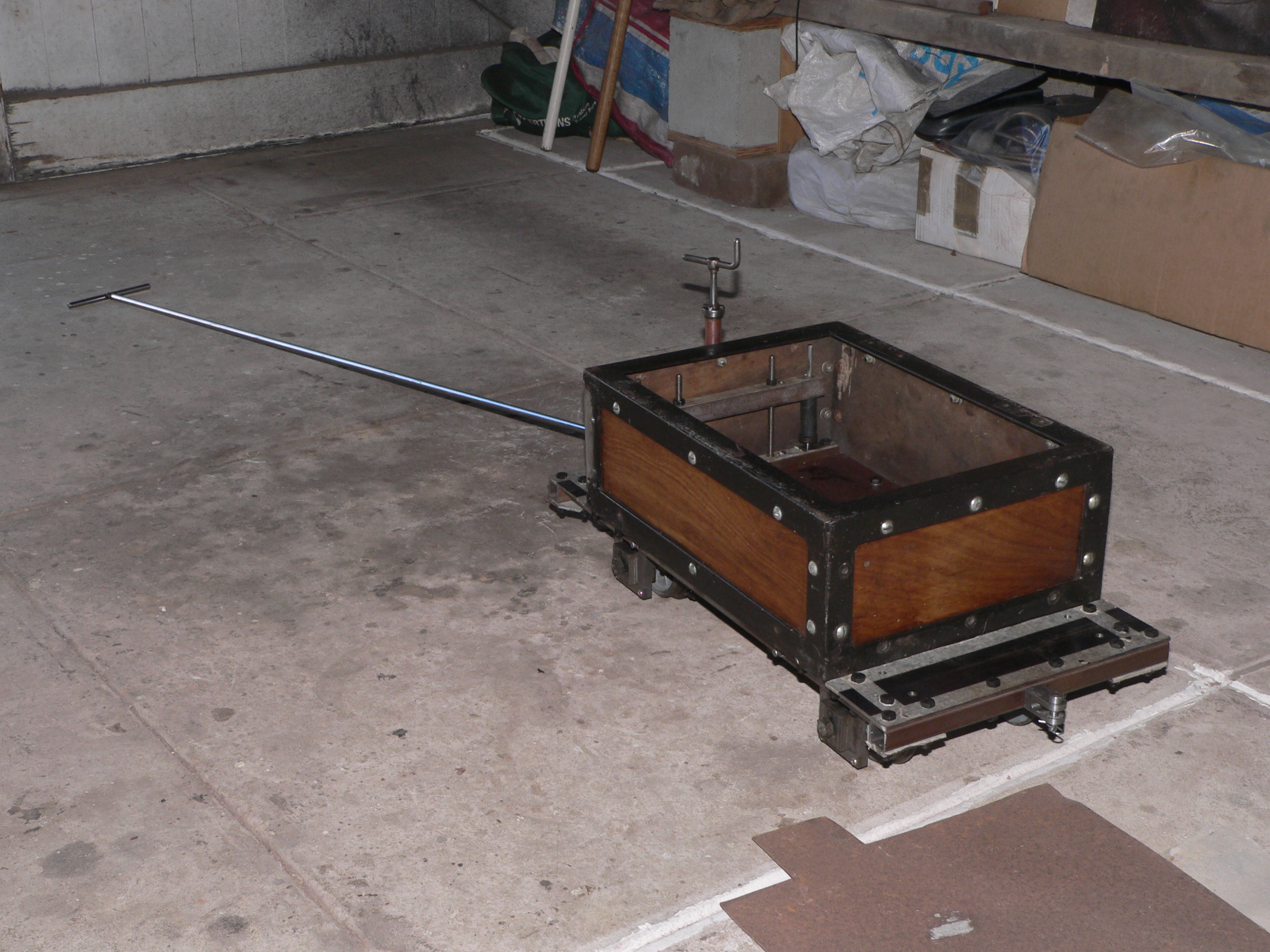
To make the truck more useful I made a long handle that connects to the front coupling. This means I can load the truck with track clearing stuff and drag the truck around while clearing the track. As well as being a useful container the truck is also good because it will derail if it runs over any sticks, etc. and provides a good test that I've cleared all rubbish off the track. Better than having a loco derail because it encounters sticks or small rocks.
After being towed around a track I realised that putting my feet on the front platform became uncomfortable pretty quickly. It's a small truck so I figured the footpegs should be as far forward as possible and as low as possible. To achieve this I made some hangers from angle iron and fitted them under the front buffer beam. The footpegs are easy to remove and will be useful if the truck is used behind a tank loco or if it's used as a brakevan.
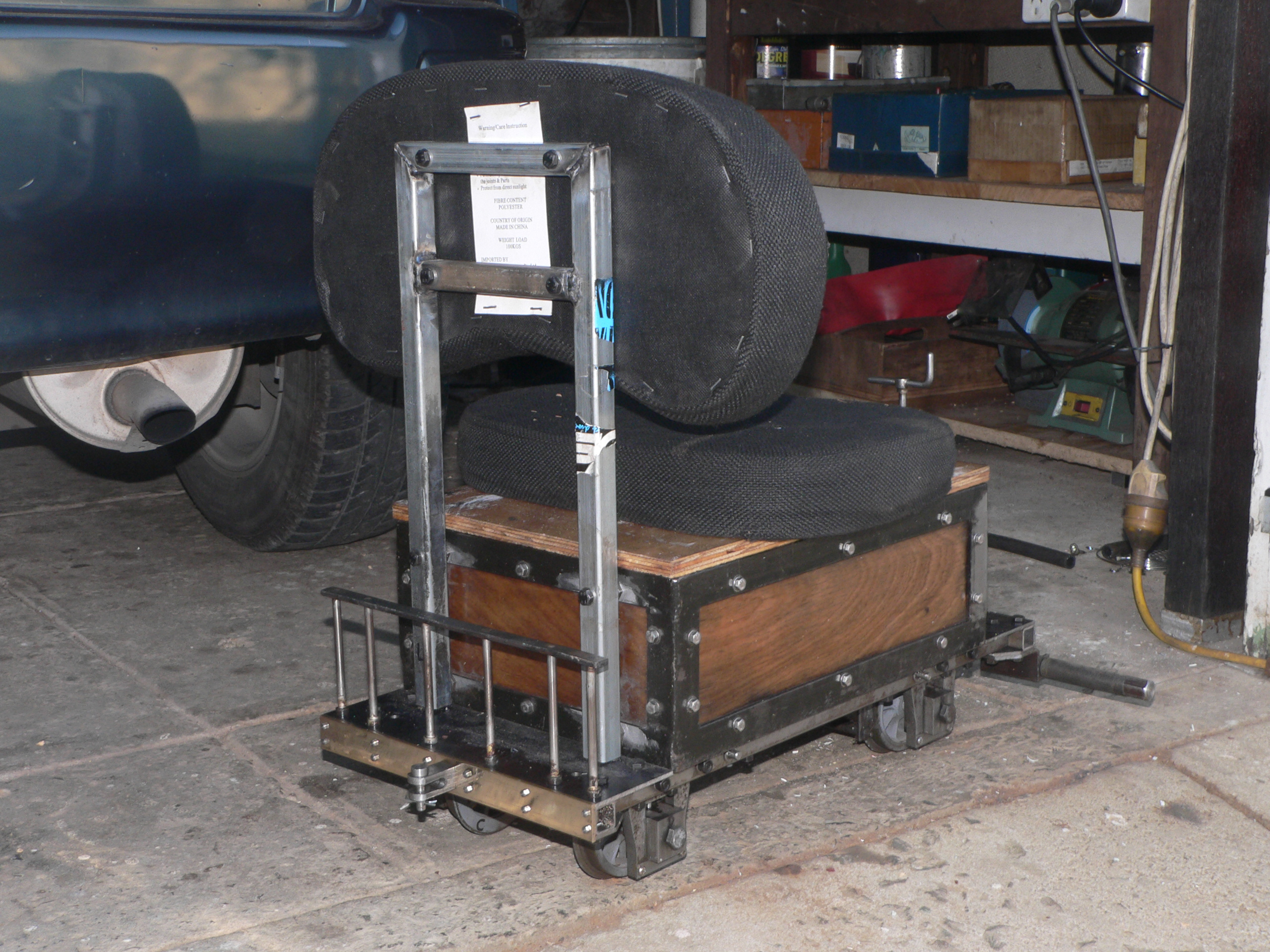
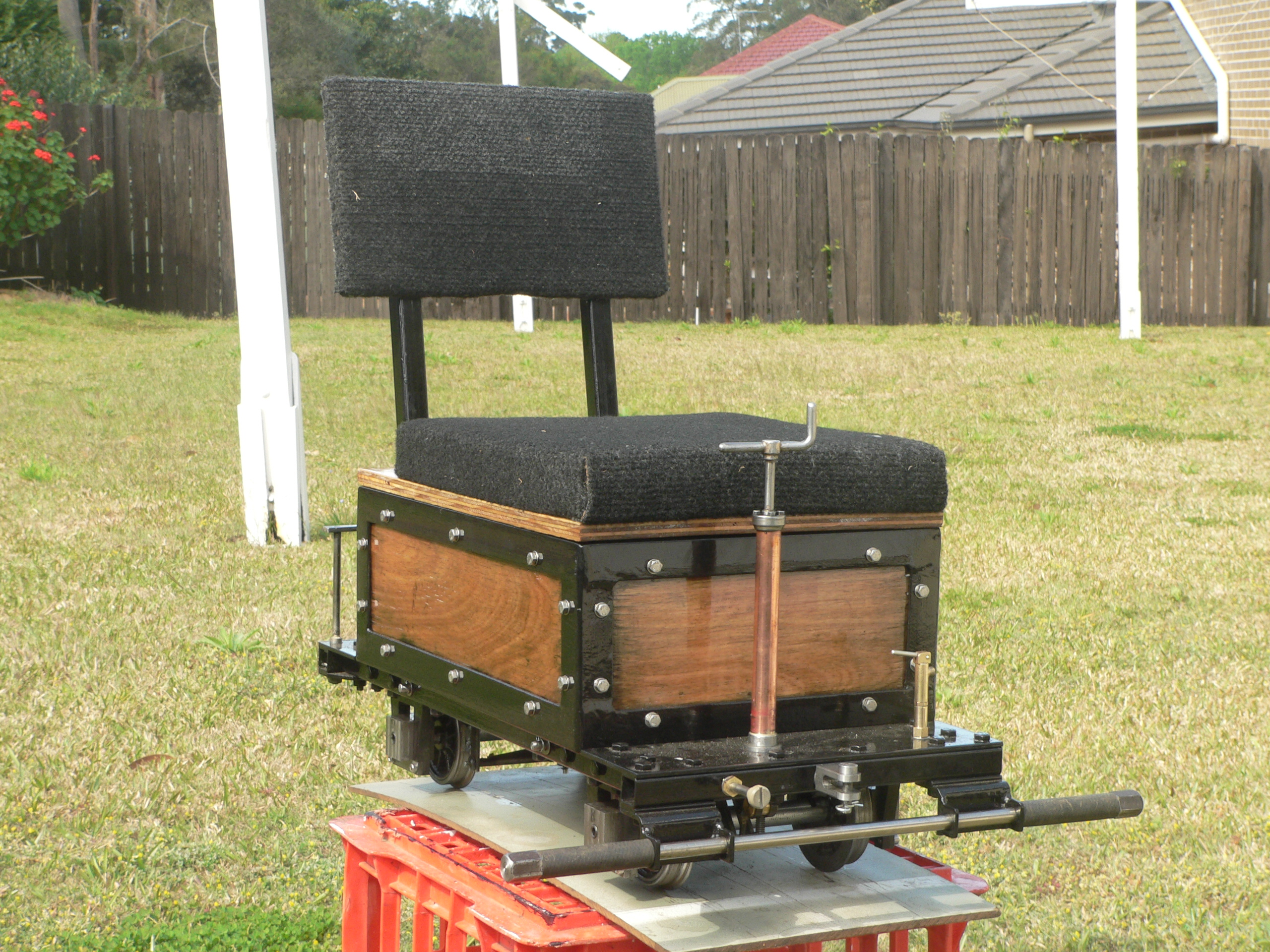
For improved comfort (hopefully) a backrest has now been fitted to the back of the box. The backrest frame slots into fittings at the bottom of the box and is bolted to the top of the box. This means it's easy to remove (undo two bolts) and yet won't fall off in an accident. The handrail at the back is partly decorative and also useful because I can keep the bannister brush I use when track clearing there and it doesn't fall off. The brass buffer beam is my attempt at model engineering.

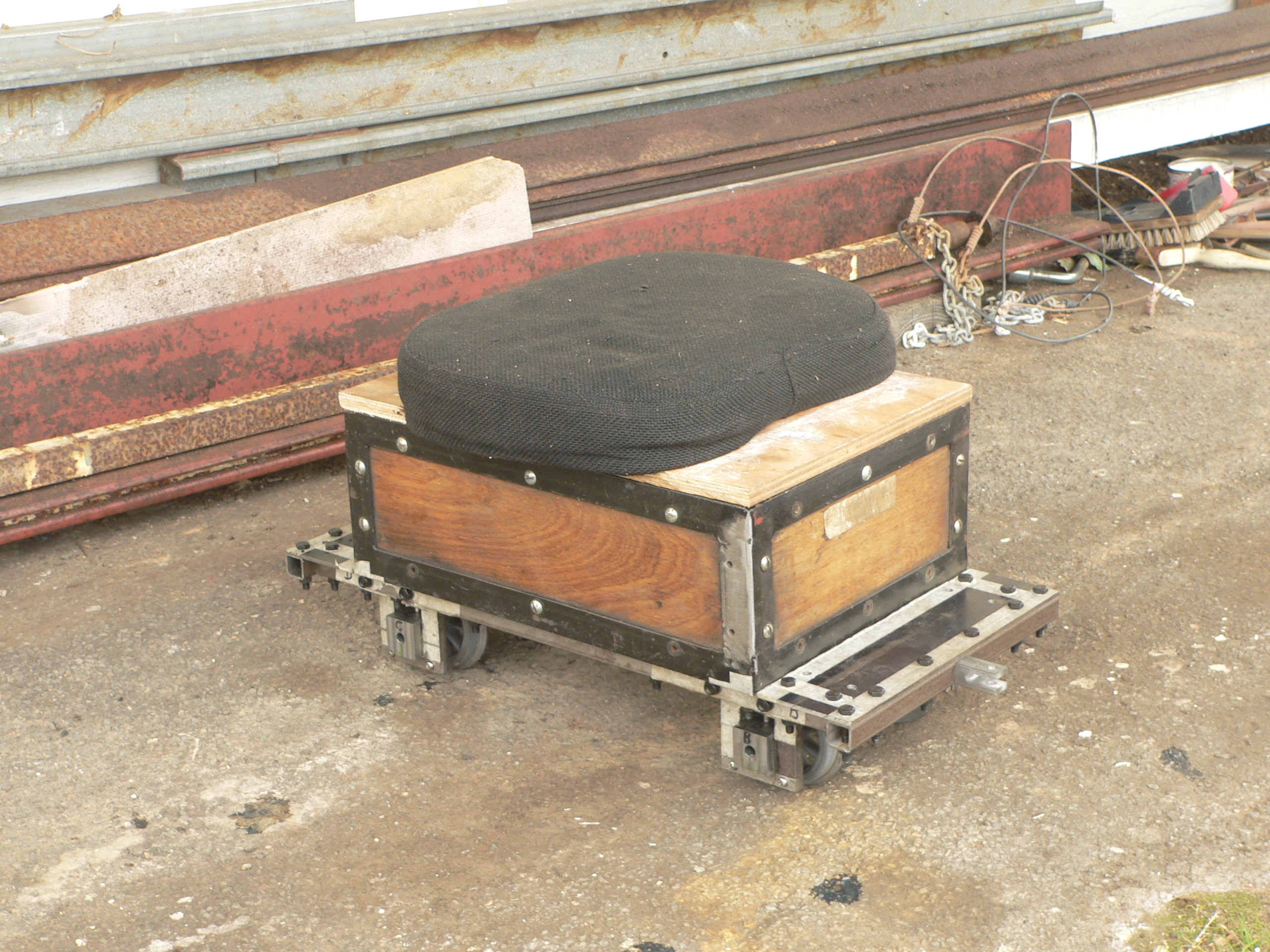
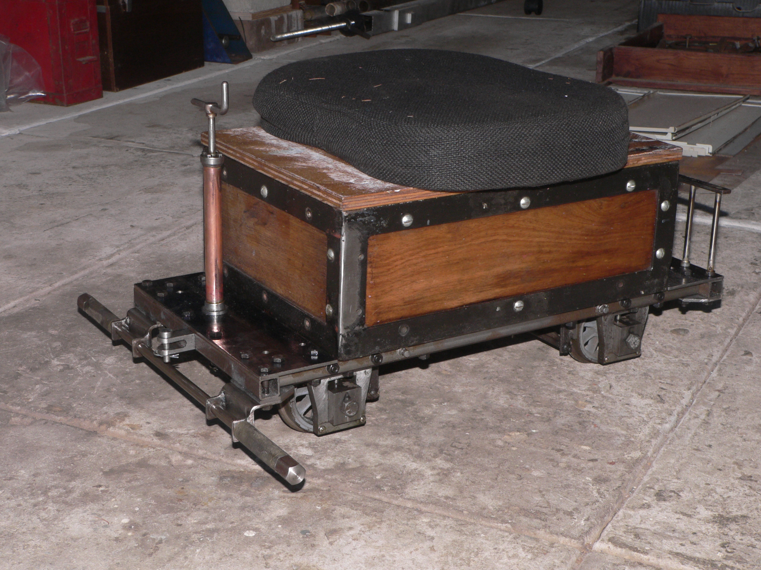
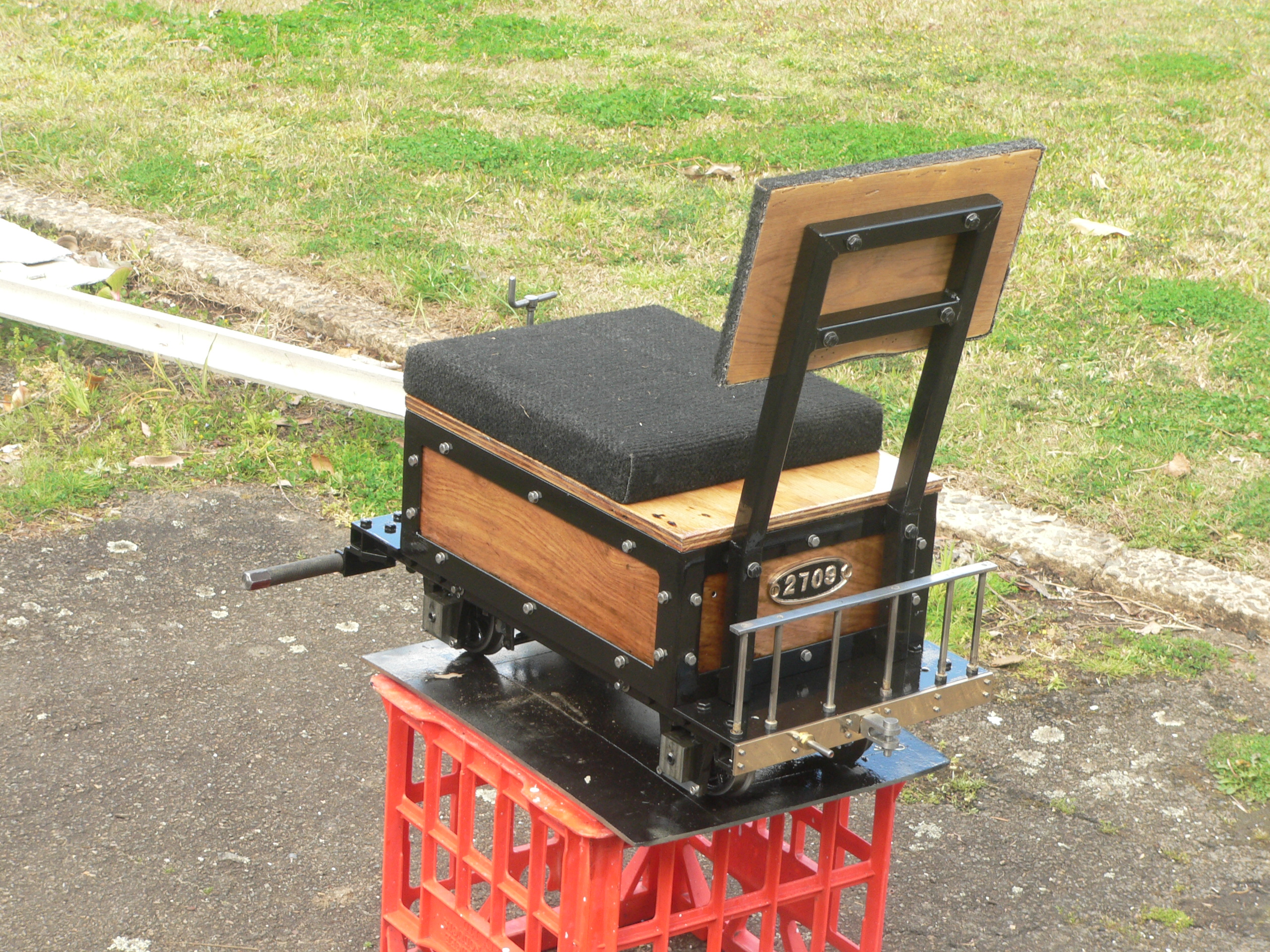
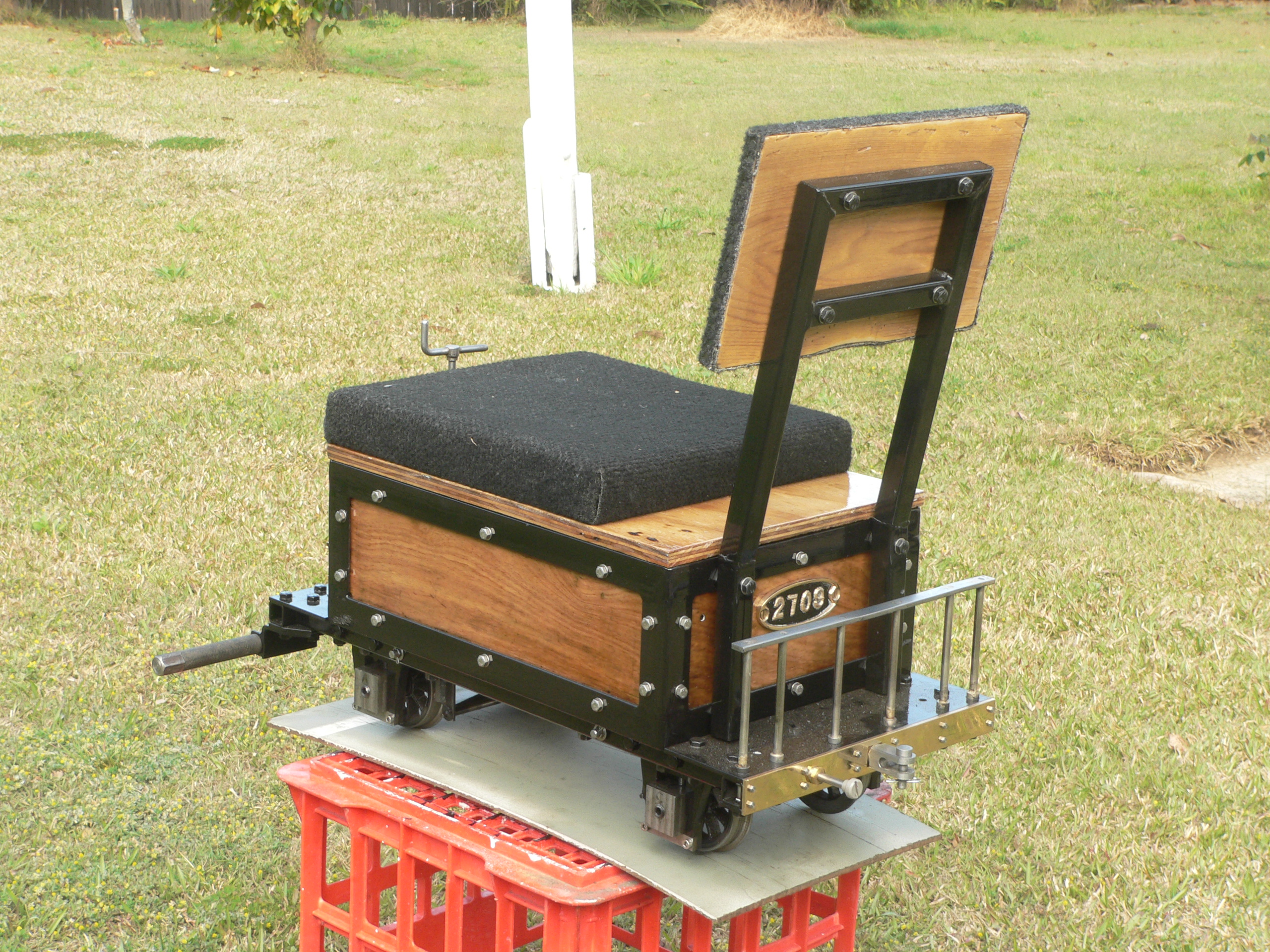
Unfortunately the excessively vertical backrest didn't work too well. Also, I didn't like the rather puffy cushions. They came from an "ergonomic" chair and were cheap rubbish filled with soft foam. I cut and welded the backrest so it reclines 12° and made a hard pad for the backrest and a felt filled pad for the seat base. The long seat base means I can sit back and use the backrest or sit forward when reaching to control a loco. And it makes this rather tiny carriage look bigger and more luxurious than it really is. The truck now has vacuum pipe connections so it can be used in a real train with carriage brakes.
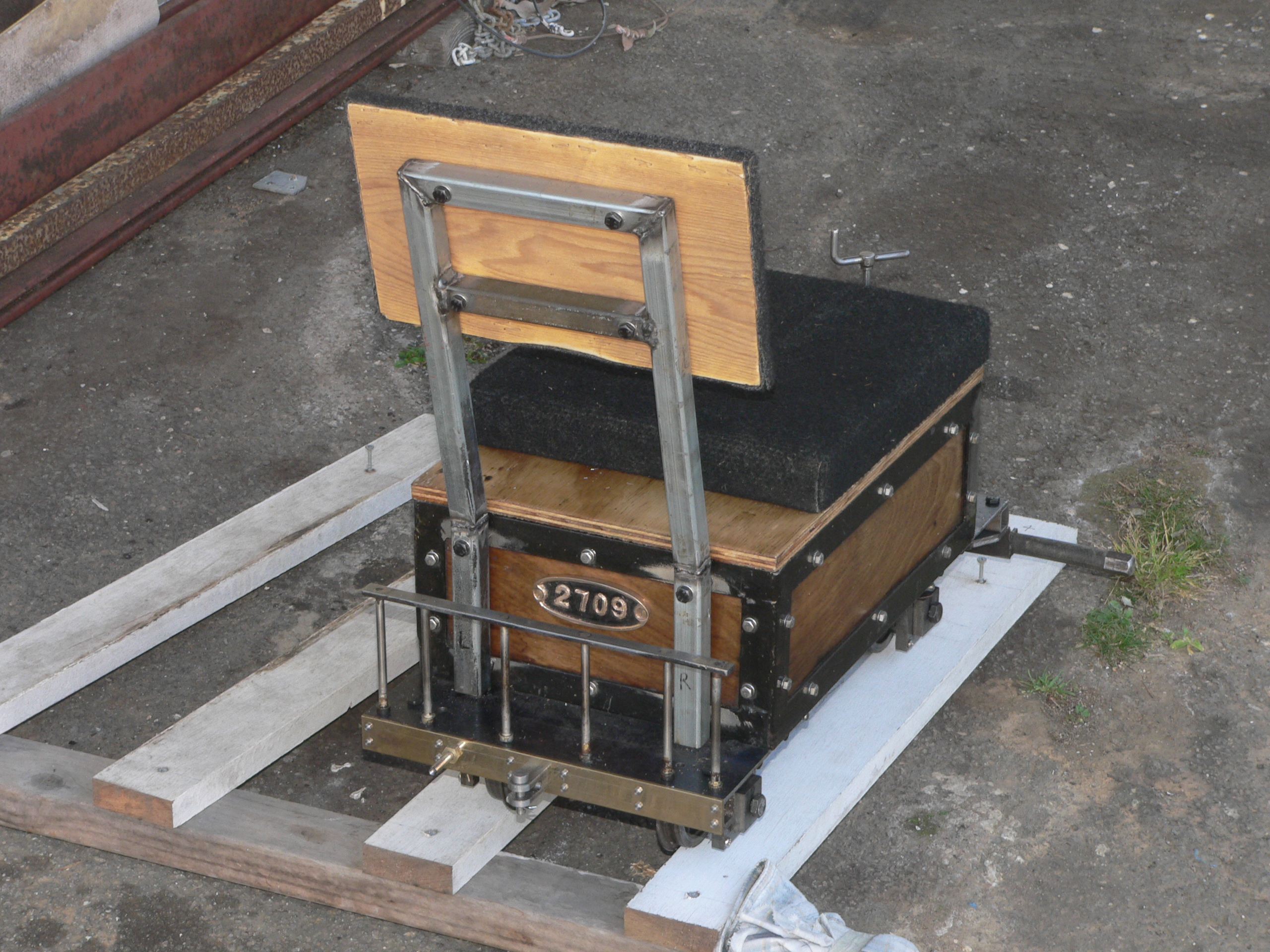
A friend gave me a plate from an NSWGR carriage (2709) so I cleaned it and decided to fit it to the back of the truck. The truck is now "2709" and I've decided the model code is "TBT" which stands for Tiny Bum Truck. I'm now thinking about making in insert for the box so the truck can be used as a tender. Holding water (maybe 6 litres) should be okay but making a coal plate and a bunker seems problematic at the moment. There is room on the front platform for an injector water valve and also a release valve for the train vacuum.
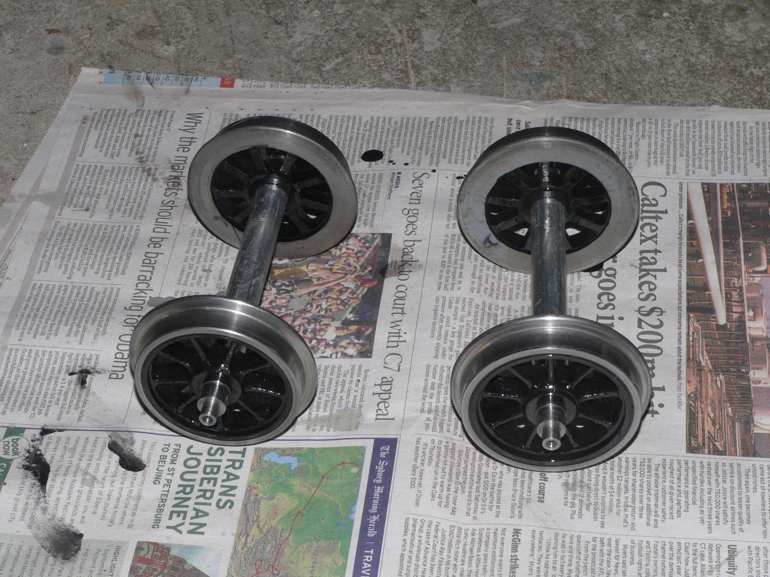
The bent axles made for a bumpy ride and the more serious thing was the extra strain on the bearings. Luckily the wheels were Loctite'd on and came off with a bit of gentle persuasion. I made replacement axles using an offcut from the local scrap yard and fitted the original wheels. Since I don't have a press the axles were finished so the wheels were a snug fit and Loctite'd on like before. It seemed like a good time to paint the truck and the next step was to dismantle the box and chassis for cleaning and painting.
Deconstruction and cleaning took longer than expected and I started painting with Ironize to seal the steel which started rusting after degreasing. Brushing the Ironize certainly did push it into the crevices but has left brush marks. The wood panels were sanded and coated with Fungishield and then Spar Varnish. The metal was sprayed with KillRust Undercoat and then Gloss Black. The wheels were brush painted (a tedious job) and then the fake tyre walls cleaned back to bare metal.
The first coat of black was way too thick and crinkled slightly when I sprayed a second coat 24 hours later. Since the surfaces aren't that good anyway I decided not to worry about it. After another three days for drying I began the stressful job of re-assembly. This went well with only a few minor hiccups.
The brakes now have proper brake shoes (with asbestos) and the couplings and vacuum pipe all match AALS standards (well, close anyway). Time for a big test run and maybe some labels (TBT 2709) for each side.

Testing showed brake problems and a wheel profile problem. Due to the new brake pads the hangers were no longer vertical and this caused the brake adjustment to vary as the axleboxes moved in the horns. The wheel profile problem was due to fat flanges and the wheel check measurement was slightly oversize. The front wheels were 79.6mm dia and the rear wheels were 76.6mm dia. I machined all wheels to 76mm dia and trimmed the flanges. This has minimised the problem with the brake hangers and corrected the flange errors.
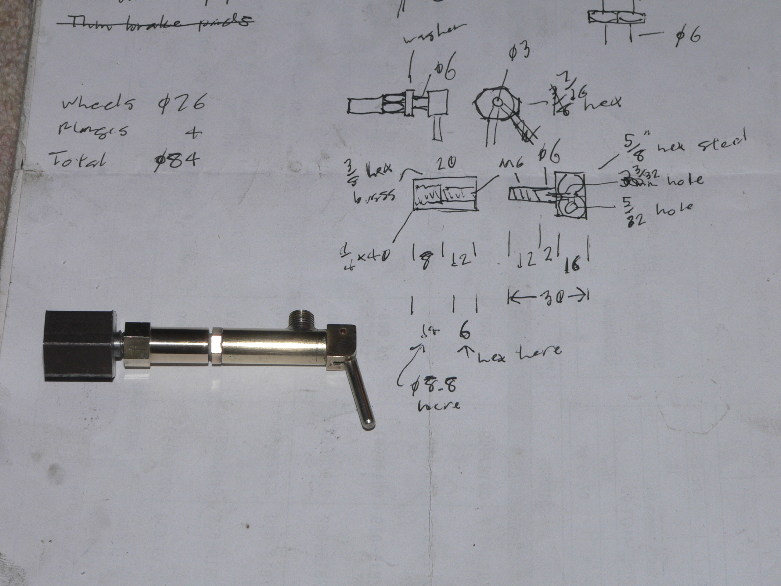
For emergency brake applications I made an adaptor for a whistle valve so it is easy to release the train vacuum. Pressing the lever opens the valve. The large base fits under the front platform and connects to the vacuum pipe.
After much more work and fiddling than was anticipated the tiny bum truck is now done. Springs and labels will happen sometime. Now it's time to get some serious value from this effort. I've made a range of coupling bars (short and long) so I can couple close when behind a tender or further away when I'm behind a carriage with endboards.
The original purpose for this vehicle was to be a bum truck for a tiny loco we were trying to fix. The loco project died and the bum truck was destined to be a track maintenance vehicle and sometimes a guard's car. After finishing this truck the loco restoration project restarted and with some work and a lot of luck the loco (SMJ 16) had its boiler approved and has been running ever since with TBT 2709 as the bum truck. The loco has an ejector for vacuum brakes and the leak valve (to apply the brakes) on the bum truck is part of the system. The only problem with the bum truck is that the brake shoes are wearing much faster than expected.
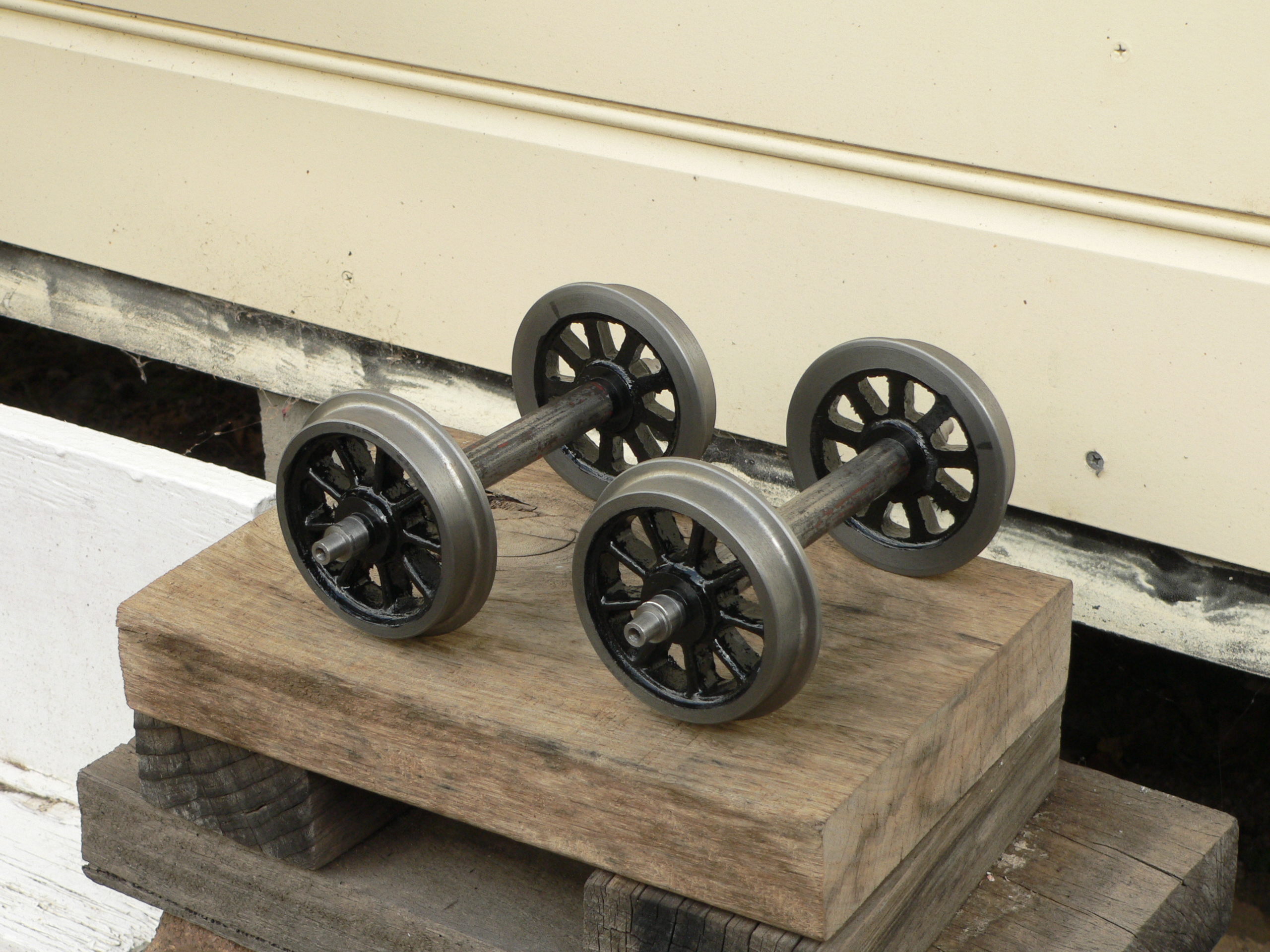
Recently (probably 2013-01-05) the flange mice attacked the back wheels and there were big chunks missing. I had derailed twice and the wheels came down on a concrete track base. The wheels had fine-scale flanges which didn't help. Luckily I'd bought some replacement wheels last year and never got round to machining them. I've now made some replacement wheelsets with the SLSLS profile (very close to AALS preferred). I'm also chasing some ready made steel wheels from Ian Ramsay. They are disc wheels and maybe not as pretty as spoked wheels but they will be much tougher.
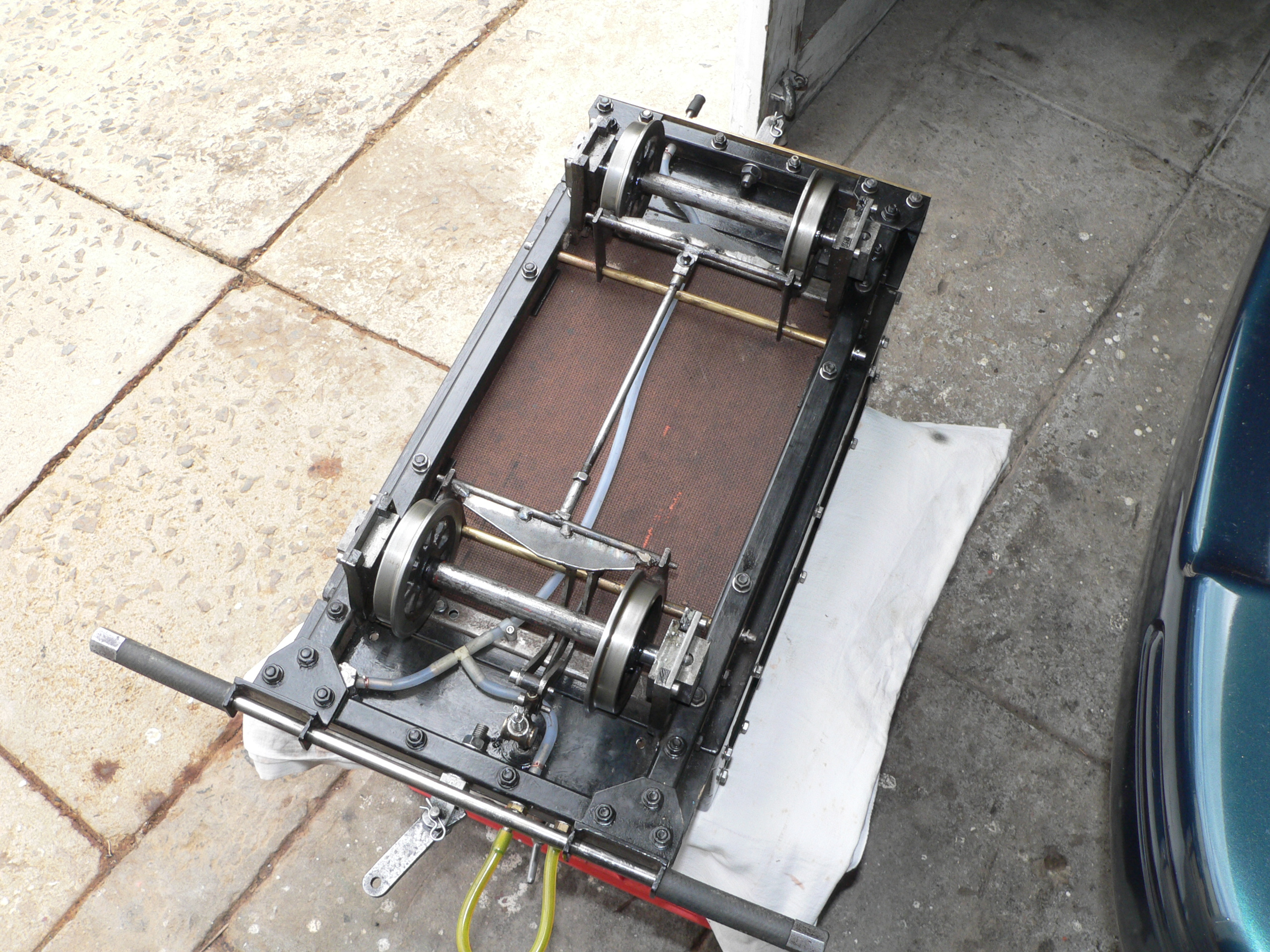
The train pipe for vacuum brakes was 3mm ID and the setup here is geared towards automatic or fail-safe brakes where the vacuum releases rather than applies the brakes. On some trains the delay when applying the brakes is alarming. Since the leak valve that applies the brakes is at the front of this truck I've replaced the 3mm piping with 4mm piping. The bore through the spigots is 1/8". I don't think these short restrictions are a problem because opening the leak valve causes the vacuum at the loco to collapse quickly even though the ejector is still working. Another change is the piping arrangement at the T-connector. Previously the leak valve and the front spigot connected to the ends and the back spigot connected to the middle port. With the ejector working and the leak valve open the airflow might reduce the vacuum reduction at the rear spigot due to the Bernoulli effect. Now the front spigot connects to the side port and the leak valve and rear spigot connect to the ends. This change should make the leak valve more effective at the rear spigot and yet not reduce the effect of the ejector. We shall see. The front brake hose (yellow) in this picture is looped back to a dummy spigot to avoid damage and dirt when not in use. The back spigot has a black cap to keep the dirt out.
Last modified 2013-01-20