
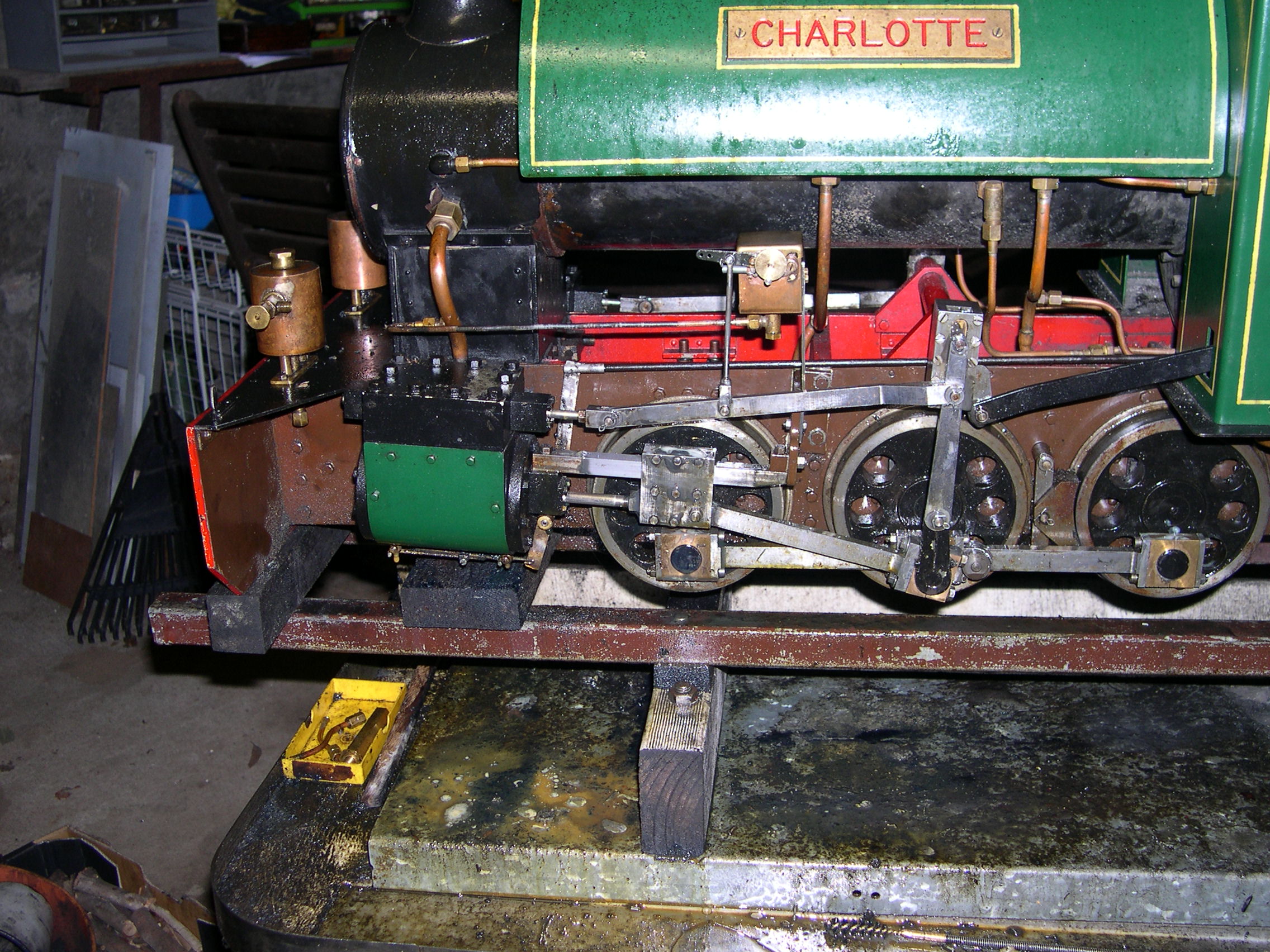
Charlotte the Starlet
|
Charlotte the Starlet |
|
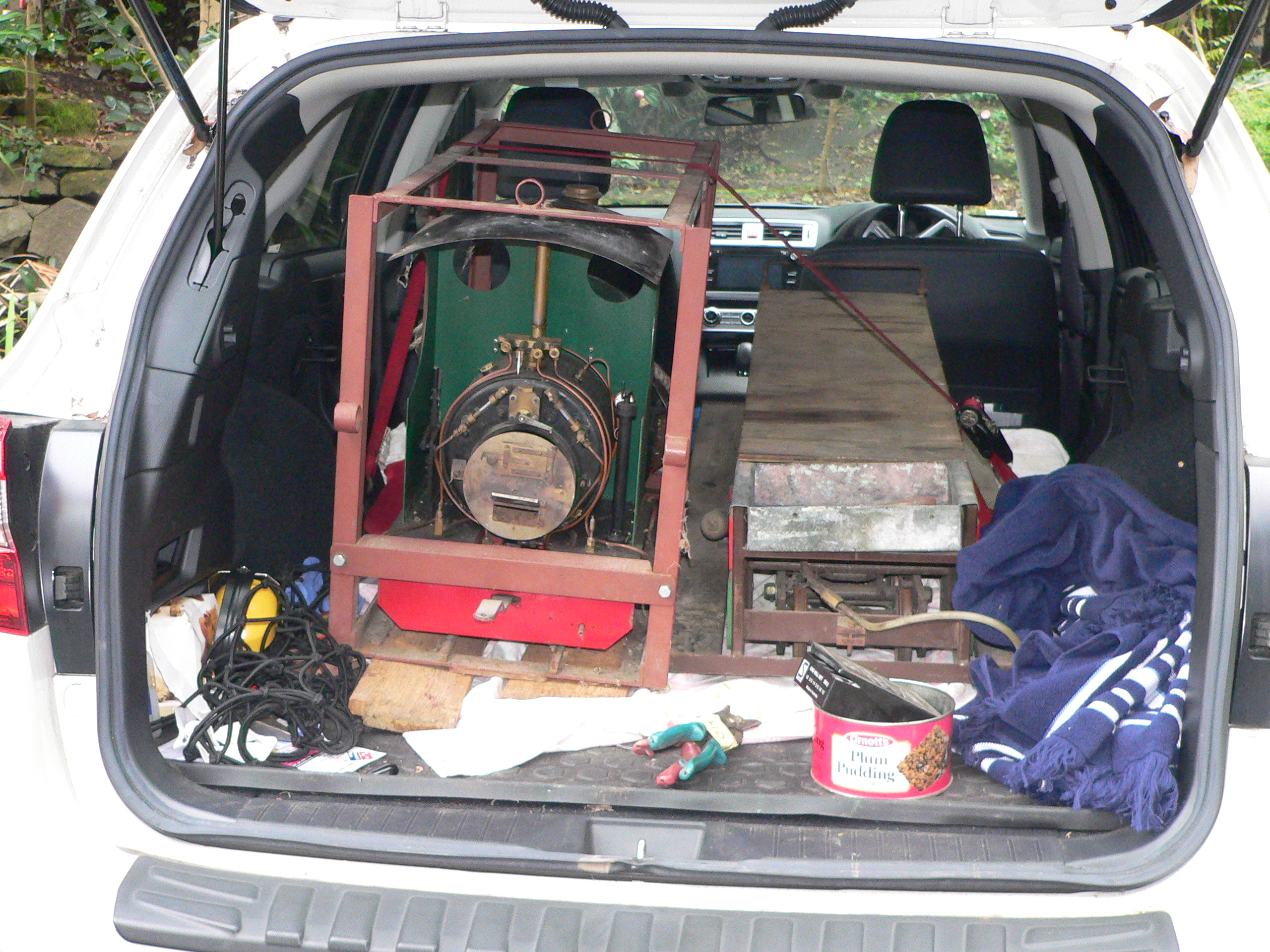
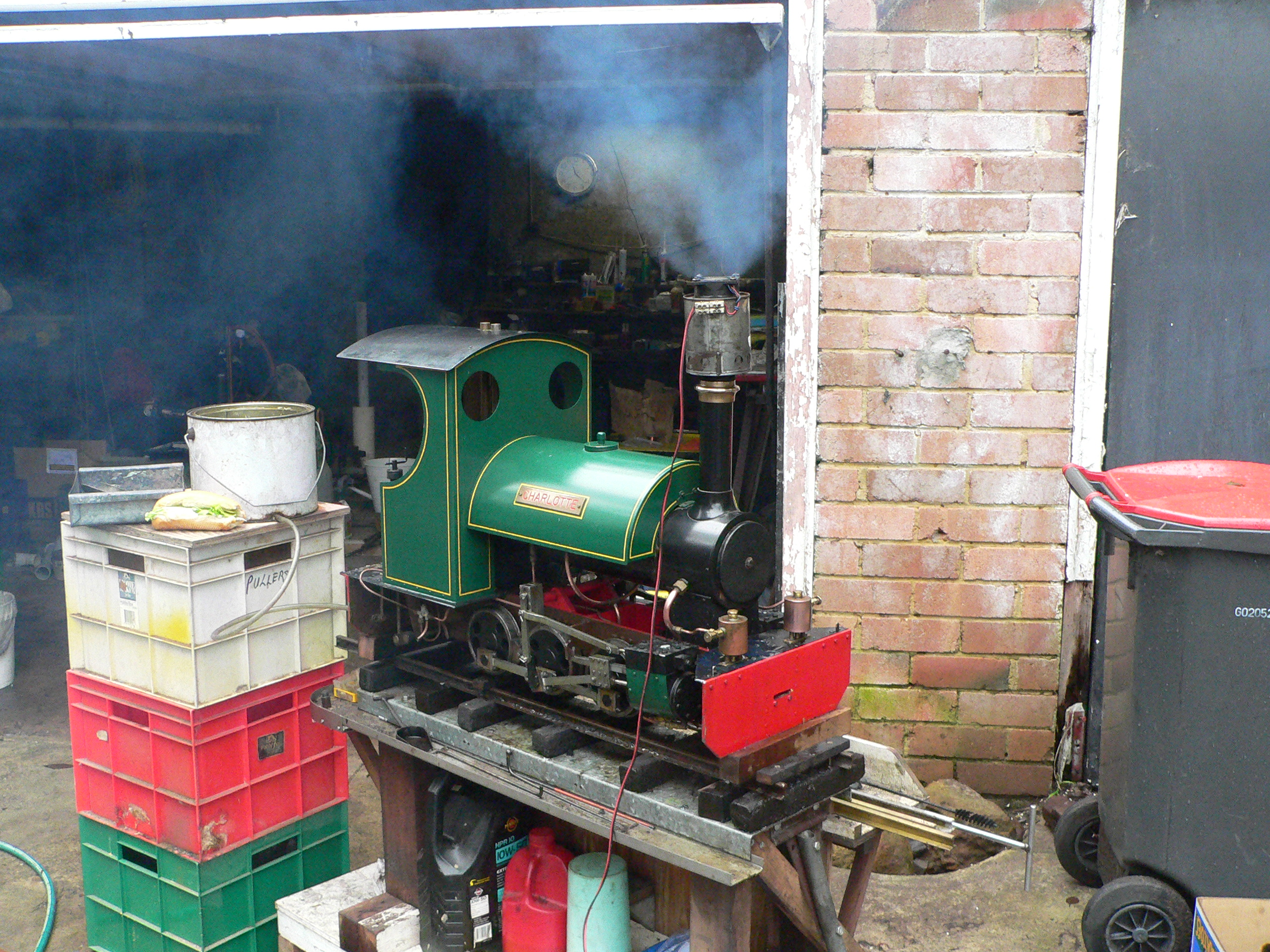
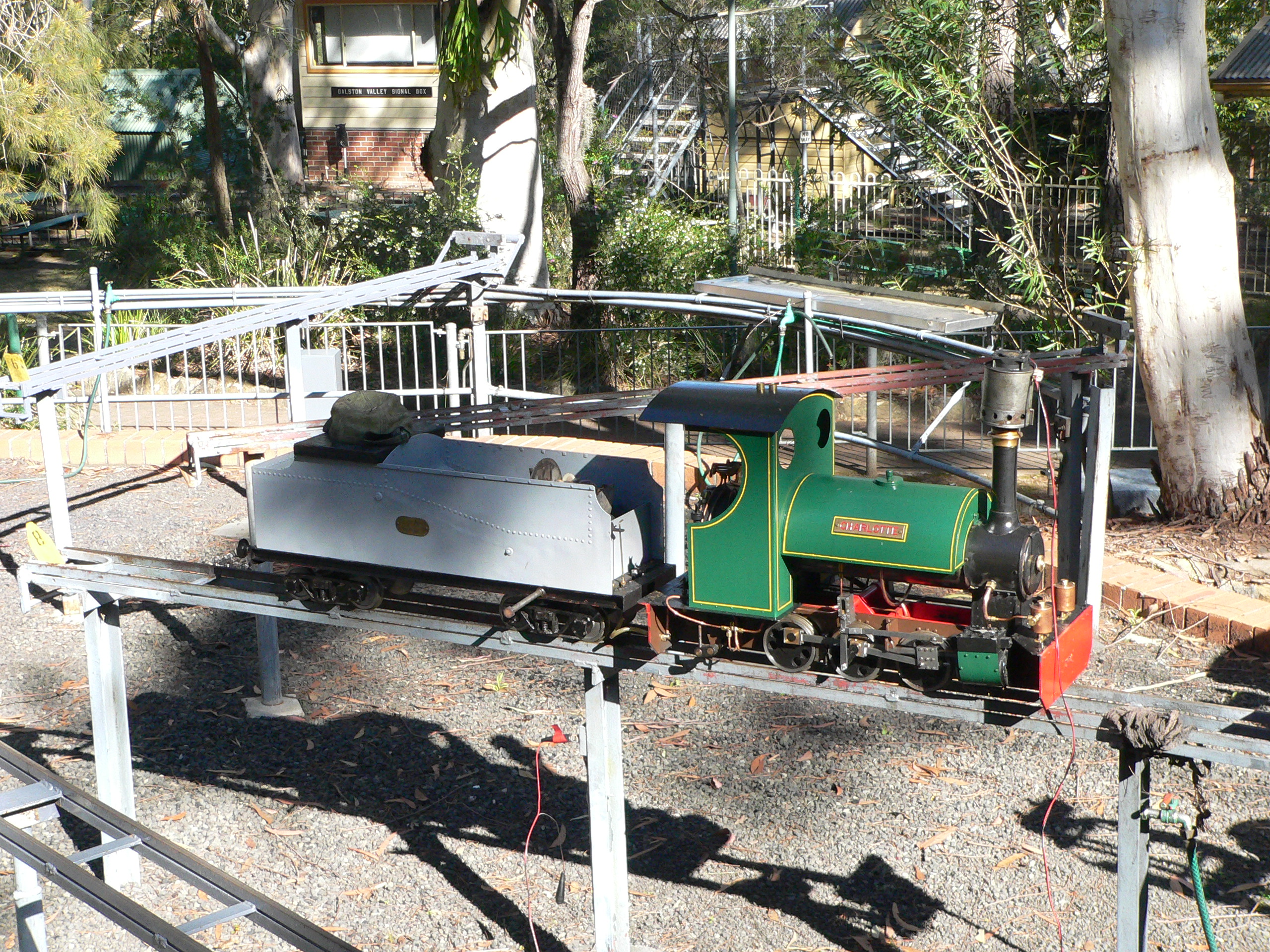
On 4th June 2017 I received an e-mail showing a loco that was for sale in Orange. The loco was part of a deceased estate and was built by Bob McKinney who was a member of Orange Society of Model Engineers. I rang Matt (the seller) and he told me some details and sent me some more pictures. The following Friday we drove to Orange and bought the loco and the riding carriage.
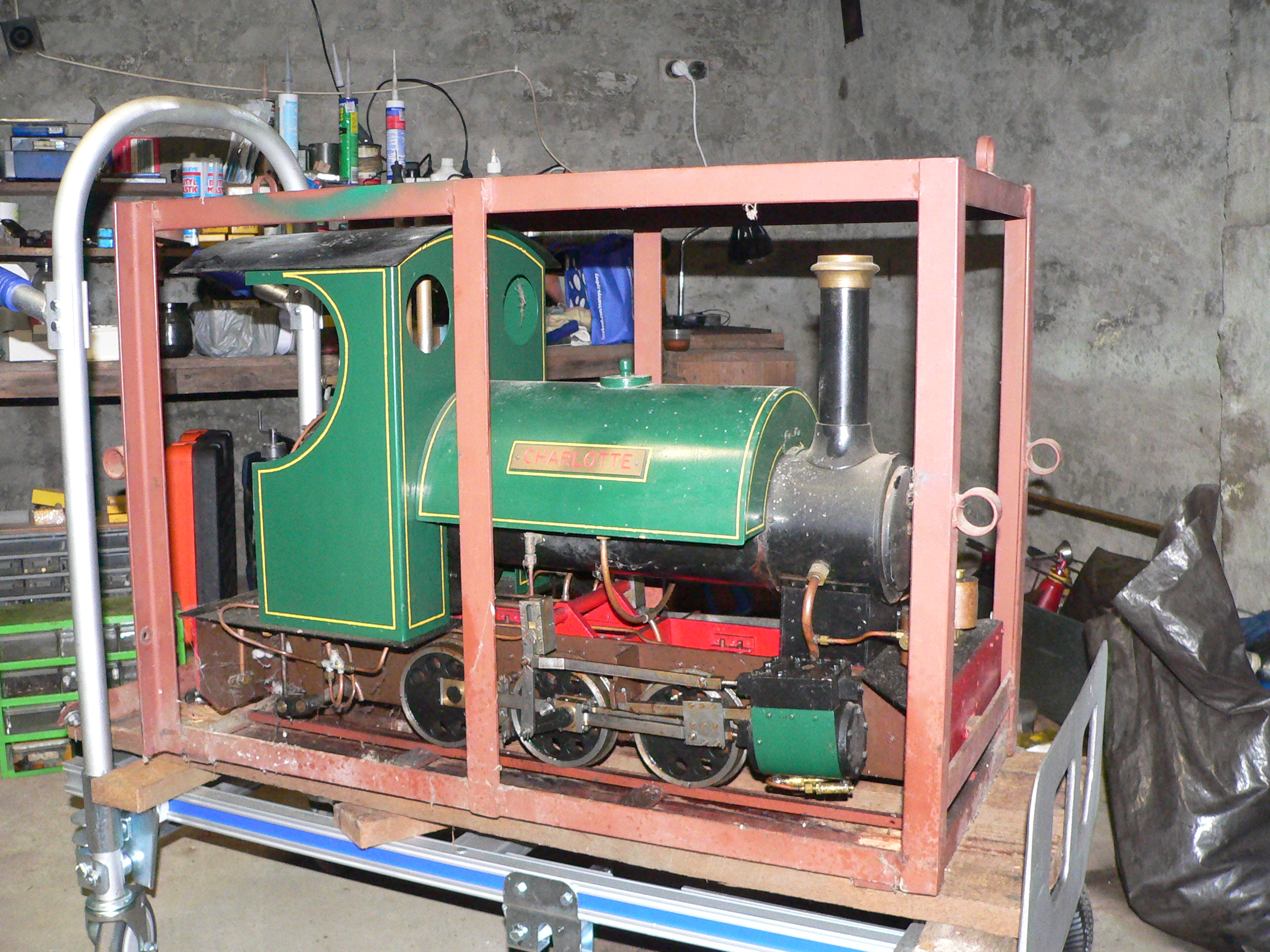
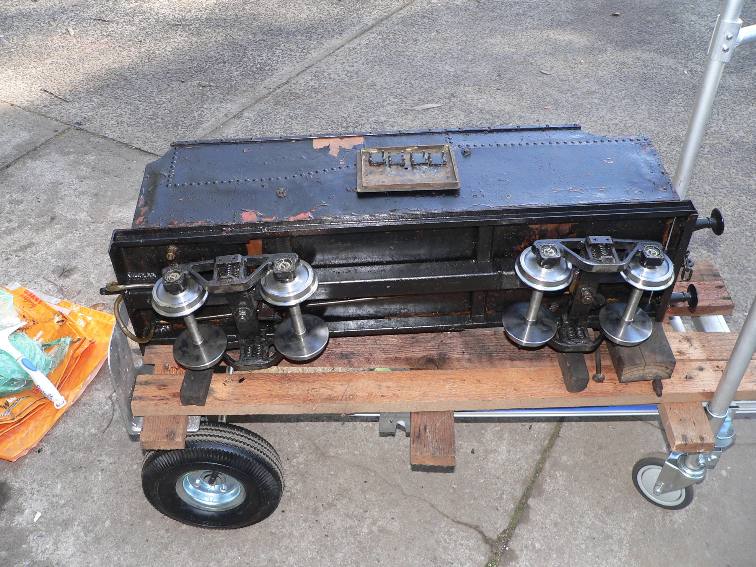
The loco is an 0-6-0 saddle tank (Sweet Pea Metre Maid) and looks like a model of a small (possibly 2' gauge) loco. It is unusual because it has a Bagnall type boiler and Hackworth valve gear. The saddle tank connects to an axle pump and the riding car has a tank for the injector. Both the loco and the riding car have manual brakes. The cab valves are for the blower, whistle, drains, and injector.
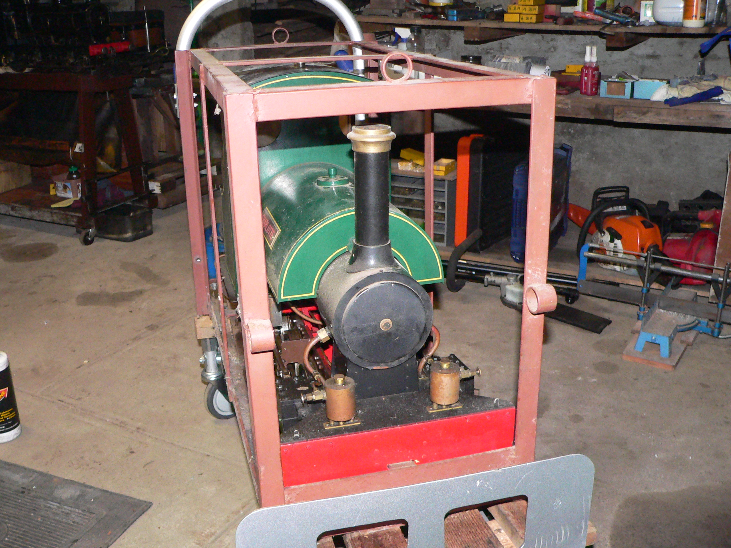
The loco seems peaceful but we're keeping it in its cage because it might have a mischievous or destructive streak. Some saddle tanks can be nasty particularly when in a new environment.
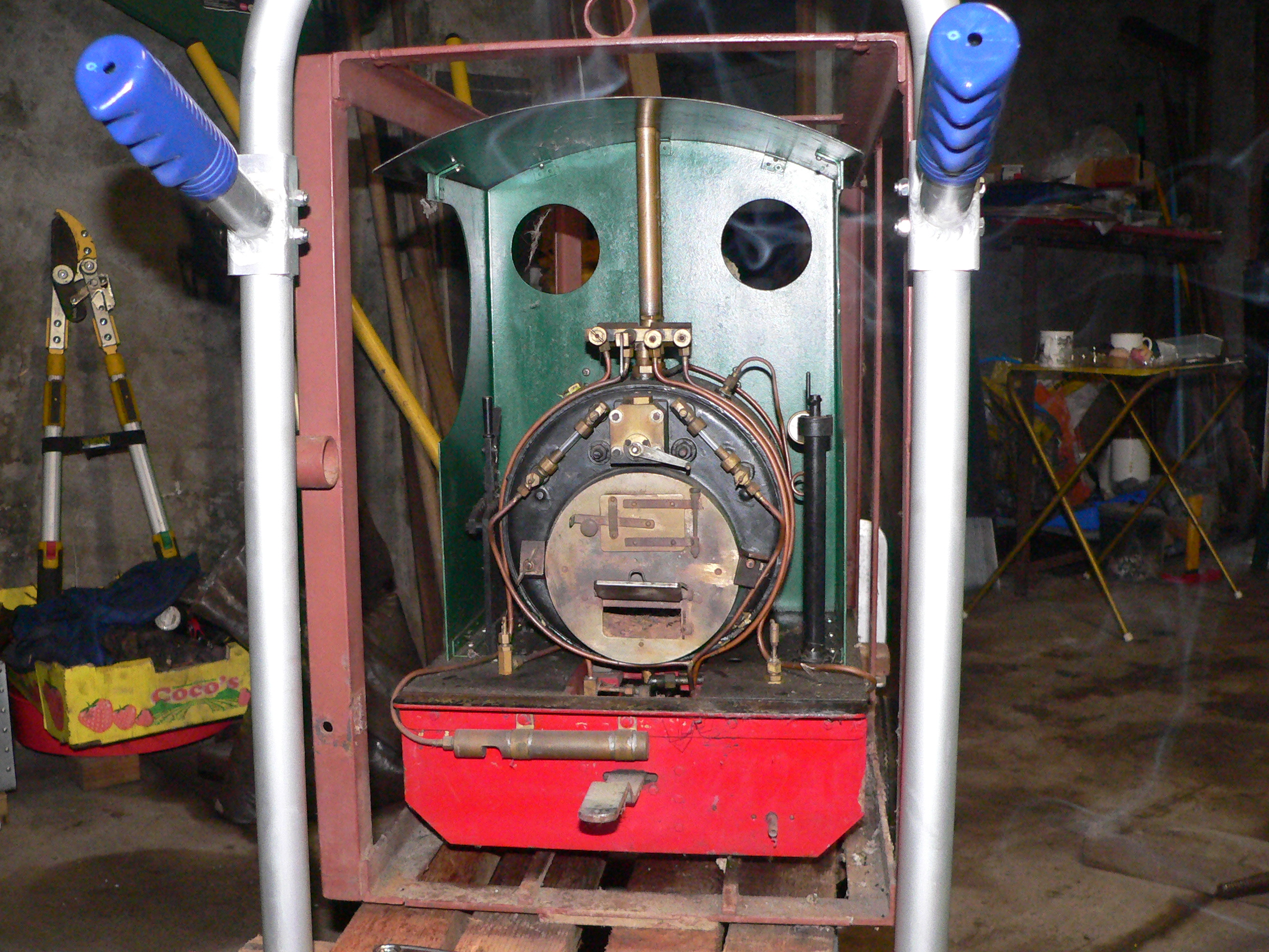

The first test was a boiler leak test using the garden hose as the pressure source. The mains water pressure here is close to 80psig which is the working pressure for the boiler. We put the loco on blocks on a stand, swapped a safety valve for a test connector, filled the boiler, and finally pressurised the boiler. The only leaks were dribbles from some of the valves. Having the loco on blocks means we can spin the wheels and check the motion.

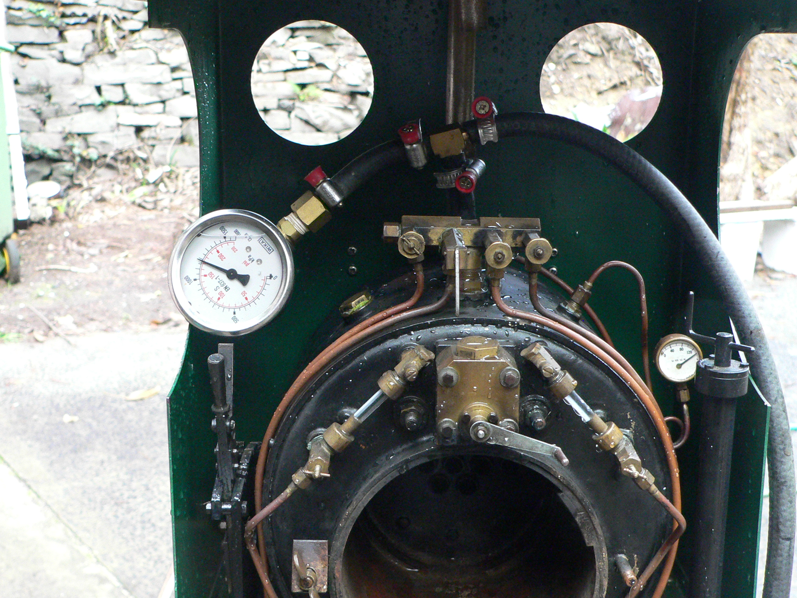
The next test was a proper squeeze to twice working pressure. For this we swapped both safety valves for a plug and the test connector. Also, the pressure gauge was replaced with a broken one because the test pressure here (160psig) wrecks the gauge. As before, the boiler showed no leaks. Notice the correct pressure reading on the big gauge and also that the wrecked small gauge is way off the dial. I wrecked this gauge doing a test years ago and I'm glad I kept it for future testing like today.
Now we could do the initial steam test. Much more fun than the water tests. We lit a fire and opened the injector steam valve to let the excess water out as the boiler heated. Once we had steam (30psig) we used the loco blower to keep the fire alight and opened the regulator. After spewing out all the oil we'd previously put in the steam chests the wheels started turning and we started testing other things. The injector worked well but we couldn't get the hand pump or axle pump to work. Other problems included a steam pipe leak in the smokebox and that the blast pipe is far too low below the petticoat.

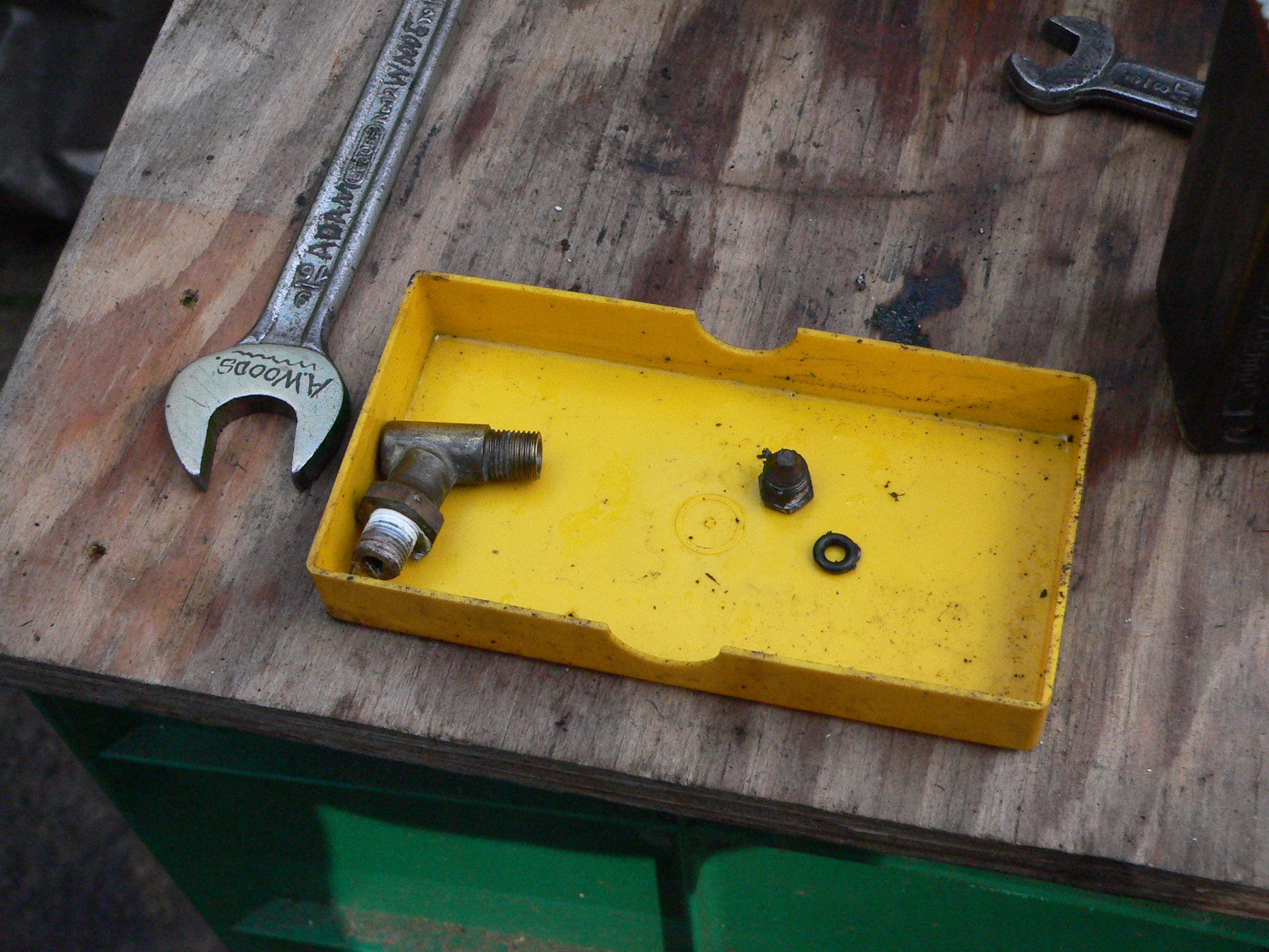
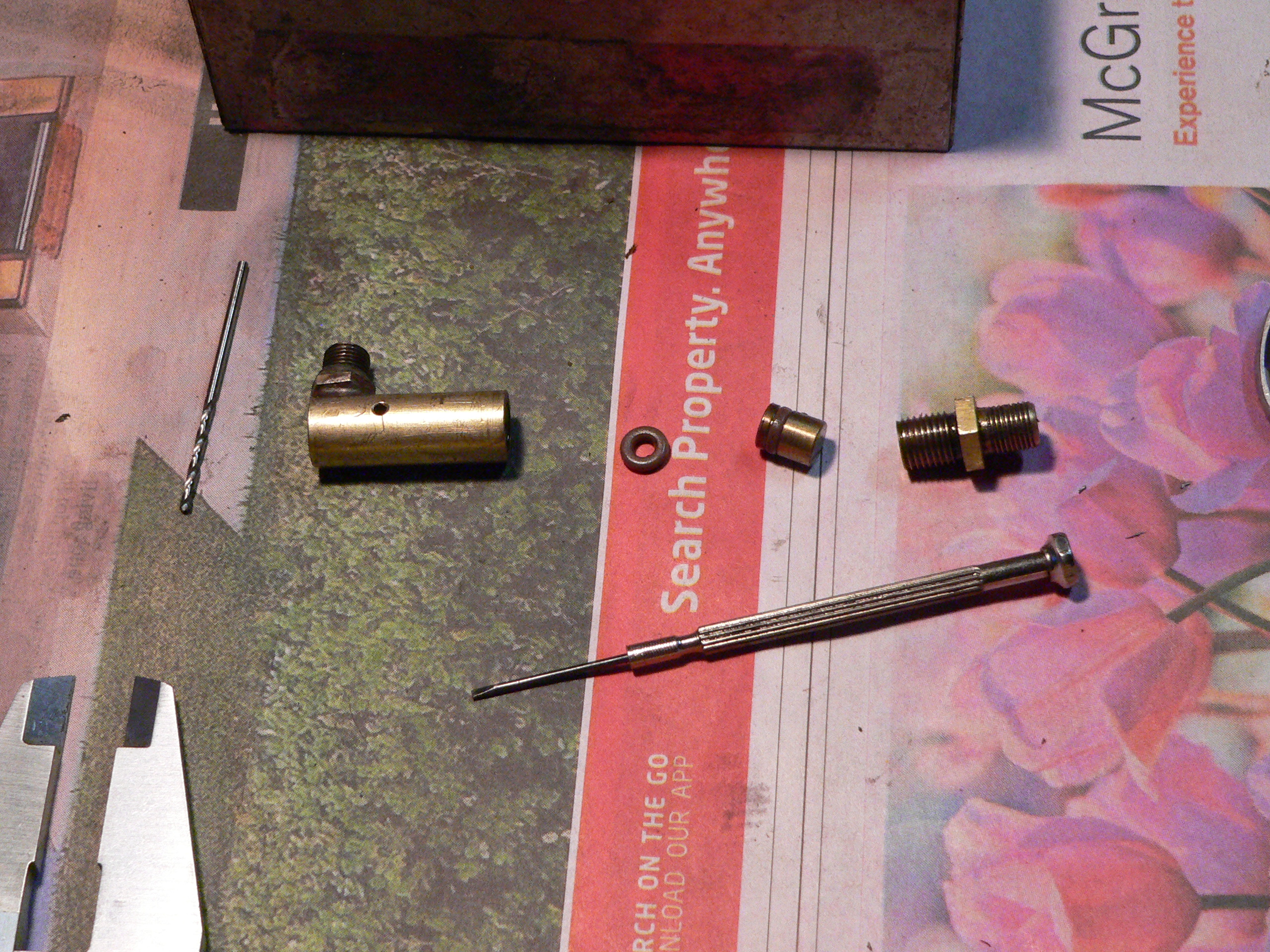
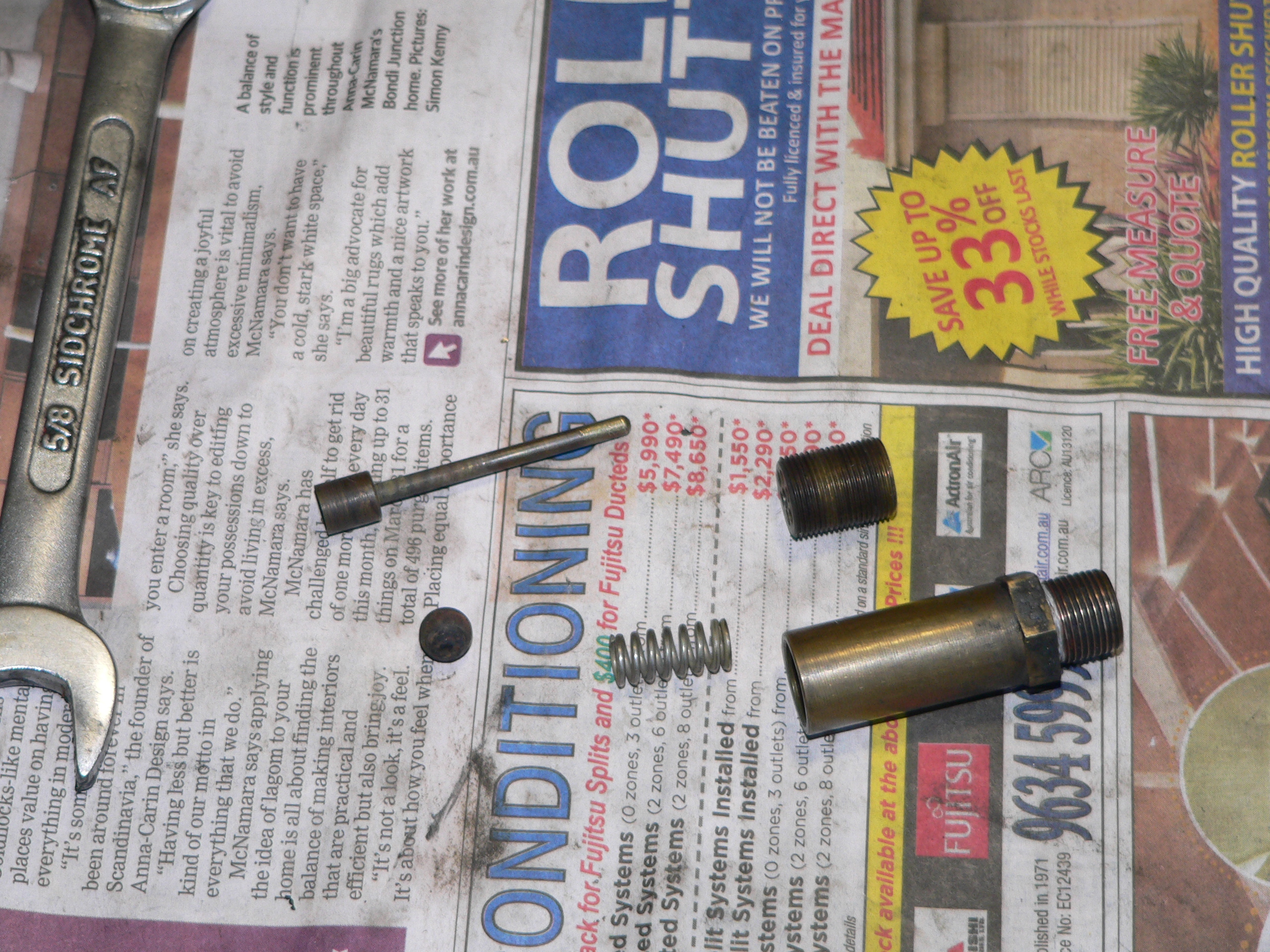
The loco has both a hand pump and an axle pump. The unusual design feature is that both pumps are in series. The hand pump kept jamming and when it did move water just leaked out the cylinder. I found that the outlet check valve was jammed closed. Freeing the check valve and replacing the O-ring fixed this pump.
After fixing the hand pump there was a terrible leak from the back of the axle pump. This pump is mounted on a frame stretcher and this stretcher forms the back of the pump. There was a rubber gasket between the pump and the stretcher and this gasket had torn. I soft soldered a brass plate to the back of the pump to seal the end of the cylinder. Replacing the gasket wasn't an option because this part of the stretcher is rusted and pitted. Both check valves were leaking so these were cleaned and the piston O-ring replaced. Access to this pump is very limited but luckily I managed to remove the stretcher and pump as one unit.
The boiler has two clack valves - one for the hand and axle pumps, and one for the injector. The pumps' valve developed a leak and started blowing water into the saddle tank. When dismantled I found the valve had a dislodged O-ring. I removed the O-ring and cleaned the seat and refitted the valve (minus O-ring) after successful testing.
Later, after filling the boiler via the injector drain, the injector clack had a bad leak. Again, the solution was to remove the dislodged O-ring, clean the seat, and whack the stainless ball. The valve now works well without the O-ring.
The cylinder drain cocks were steam powered and most stuck closed. The drain cock piston has an O-ring and the piston also pushes against an O-ring to seal the cylinder outlet. Testing showed that when "stuck closed" it's not the piston that jams but that when the piston moves back to uncover the drain hole the front O-ring also moves back and covers this hole.

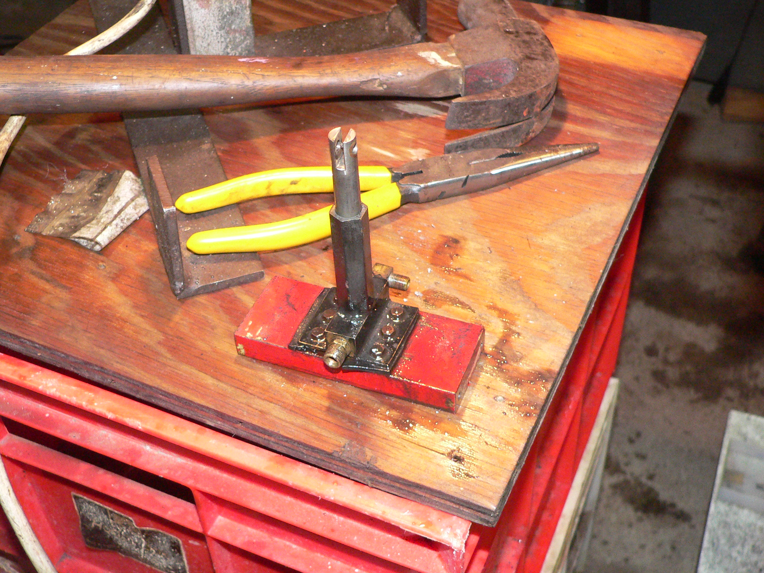
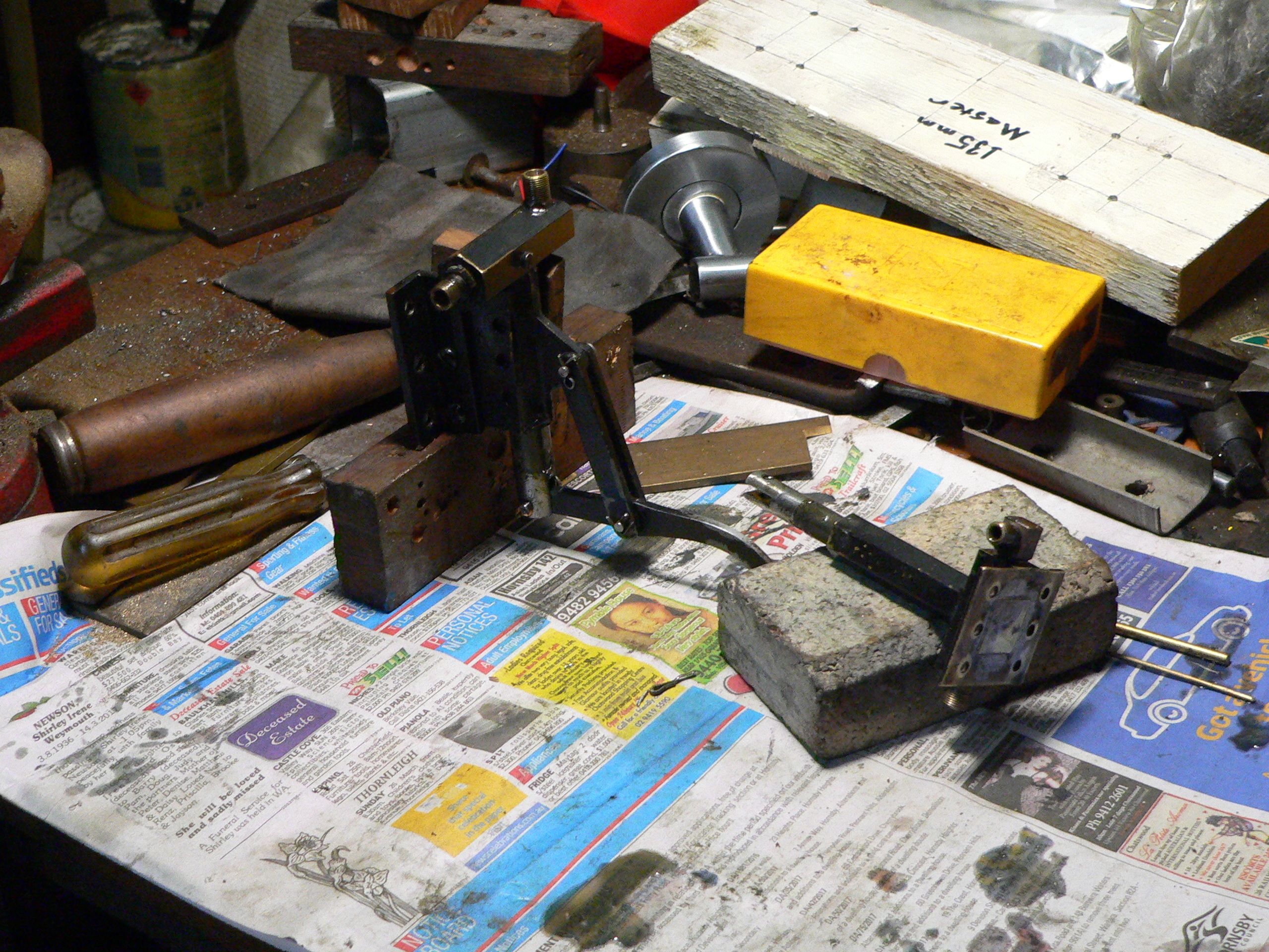
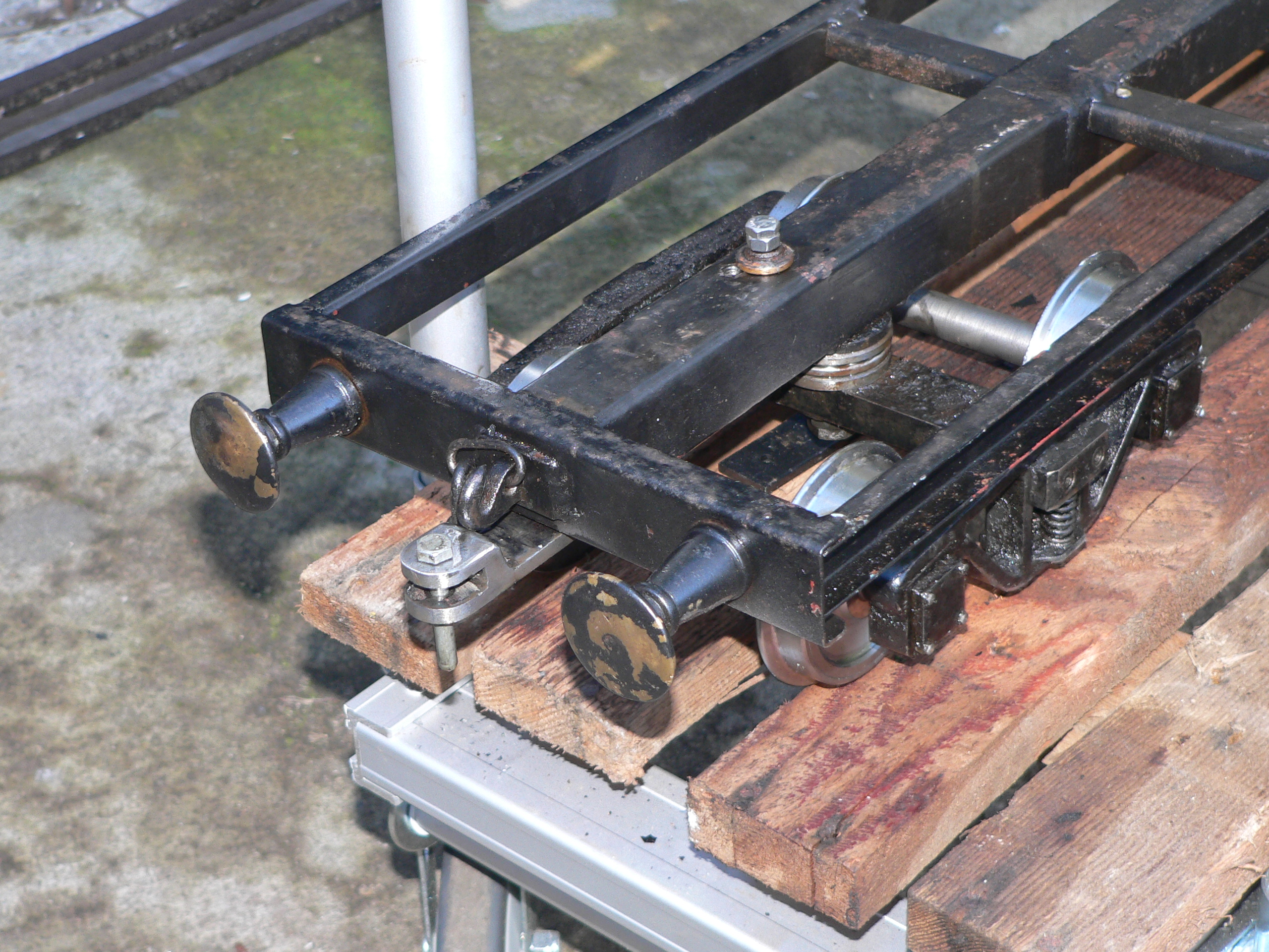
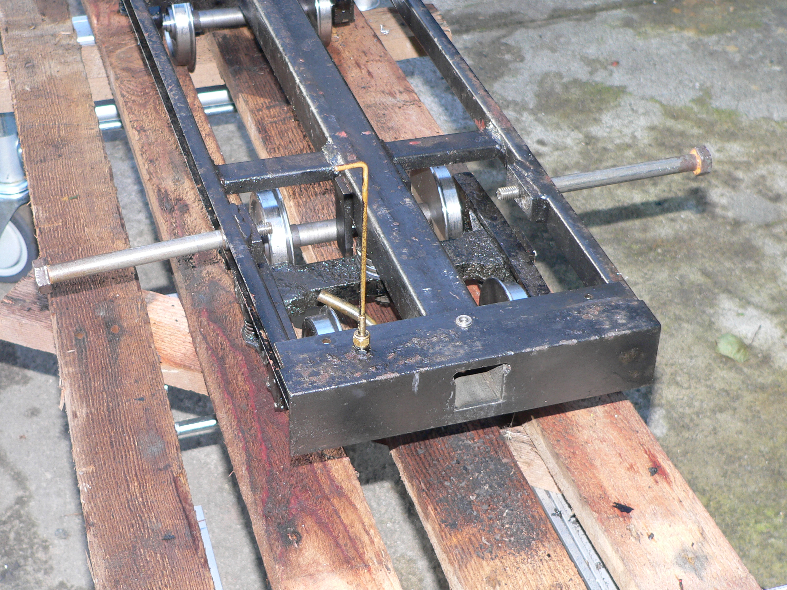
The solution here was to replace the steam-powered drain cocks with manual ones. This required drilling a 4mm hole in each frame for the actuating rod. The first photo shows the jig used to guide the drill. The jig is located by a bolt in a frame stretcher hole, aligned by the square, and locked by the clamp. The second photo shows the crude levers and rods that link everything together.
The blast pipe didn't create a proper draught and the loco needed the blower on to keep the fire alive. The blast pipe was 80mm below the petticoat which is 40mm ID. To achieve the recommended gradient from the blast pipe to the petticoat I fitted a 22mm high extension to the blast pipe. This improved the draught but the loco still struggled on the first test run. I reduced the blast pipe size from 1/4" to 7/32" and also cleared the chimney which was heavily coated with a sticky mess of ash and oil.
The blower is a piece of 1/8" tube pointing up the chimney. To improve its efficiency I fitted a restrictor to the end of the pipe. Without this most of the steam pressure is lost as the steam flows from the blower valve to the smokebox end of the pipe. The blower jet(s) area must be less than the area of the pipe to reduce this loss.
Now I've installed a new petticoat because I figured the chimney diameter is far too large. The petticoat is 22mm ID, 90mm high, with a flared extension at the bottom. The distance from the blast nozzle to the throat is 30mm (this should have been 35mm but I miscalculated when installing the petticoat in the sealing bush in the base of the chimney). This gives me a 1 in 2 cone touching the nozzle and the throat, and a 1in 6 cone to the top of the throat. By a fluke I also get a 1 in 6 cone to the top of the 41mm ID chimney.
Subsequent to this picture I trimmed 5mm off the top of the blast nozzle to compensate for my miscalculation. The petticoat makes it harder to access the nuts securing the chimney so I took the easy approach lowering the nozzle rather than removing the chimney so I could raise the petticoat.
While experimenting here I made two replacement blast nozzles both 5mm ID. One was for a 40mm gap to the petticoat throat and the other was for a 50mm gap. The first test was to start with 25psi and run the loco on blocks with no blower and see if this would raise boiler pressure. The 40mm gap nozzle worked okay and the 50mm gap seemed even better. Then I tested with the brake partially on to simulate a load. Again the 50mm gap nozzle worked well. The picture shows the smokebox with this short nozzle.
I have to say that I don't notice any great difference between the performance with the different nozzles. The gap range is 30mm to 50mm. The throat is over 90mm high which might be too much (I'd like at least 70mm). I might remove the petticoat and flare the top. The next test will be a proper track test hauling some carriages.
With the very tall chimney I do notice that I get condensation in the upper wide portion and this drips back into the smokebox. Tha same happened before I installed the reduced bore petticoat.


I rang Ben de Gabriel at Bathurst to ask for contact details for the boiler inspector at Orange. He gave me Roger Kershaw's number and when I spoke to Roger he said he remembered the loco and would post the boiler history. Sure enough, the required documents turned up a few days later. These documents record that the boiler was approved and I needed this record for a renewal inspection. I then rang Brian Day (our inspector) to request an inspection.
On 24th June 2017 I took the loco to Galston Valley Railway (Hornsby Model Engineers, my club) for the boiler inspection. The squeeze (cold hydraulic test) went for 20 minutes and no leaks were found. The steam test after took a while because the boiler was left full of water and again all was deemed okay.
I then ran the loco for a few hours. The children had a great time travelling behind a steam loco. The loco pulled well but I had trouble keeping the fire active and the steam pressure up. Firing certainly is a "little and often" affair on this loco. I'd like a longer regulator handle for better control. And maybe footpegs on the loco so I can stretch my legs.

The safety valves opened a little early (about 70psig) and kept leaking even once the pressure dropped. I dismantled the valves and found that the stainless balls were badly encrusted. Replacing the balls and cleaning the seats helped here.
Before re-assembly I made and fitted some collars to keep the springs central on the spindles. Previously they could drift sideways a bit and apply uneven force to the spindles and seats,
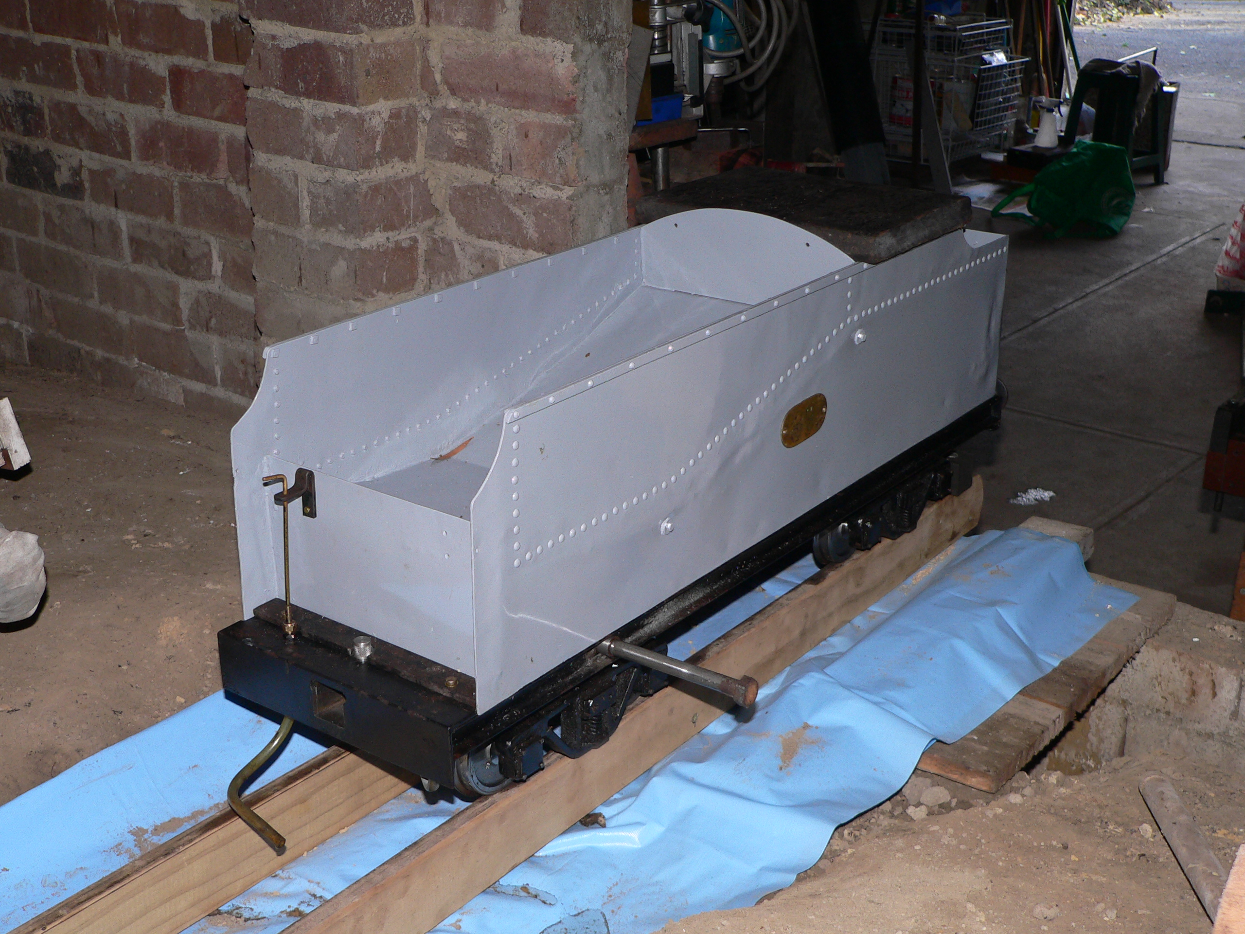
Charlotte came with a riding car containing a coal tray and a water tank for the injector. This car is good because it has brakes but is overwidth (500mm) for Galston (my track) and the ride is hard because the bogies are unsprung. We had a spare tender which was unusable because the wheels were badly rusted and in fact some of the flanges were missing. So we removed the wheelsets and checked the ball races.
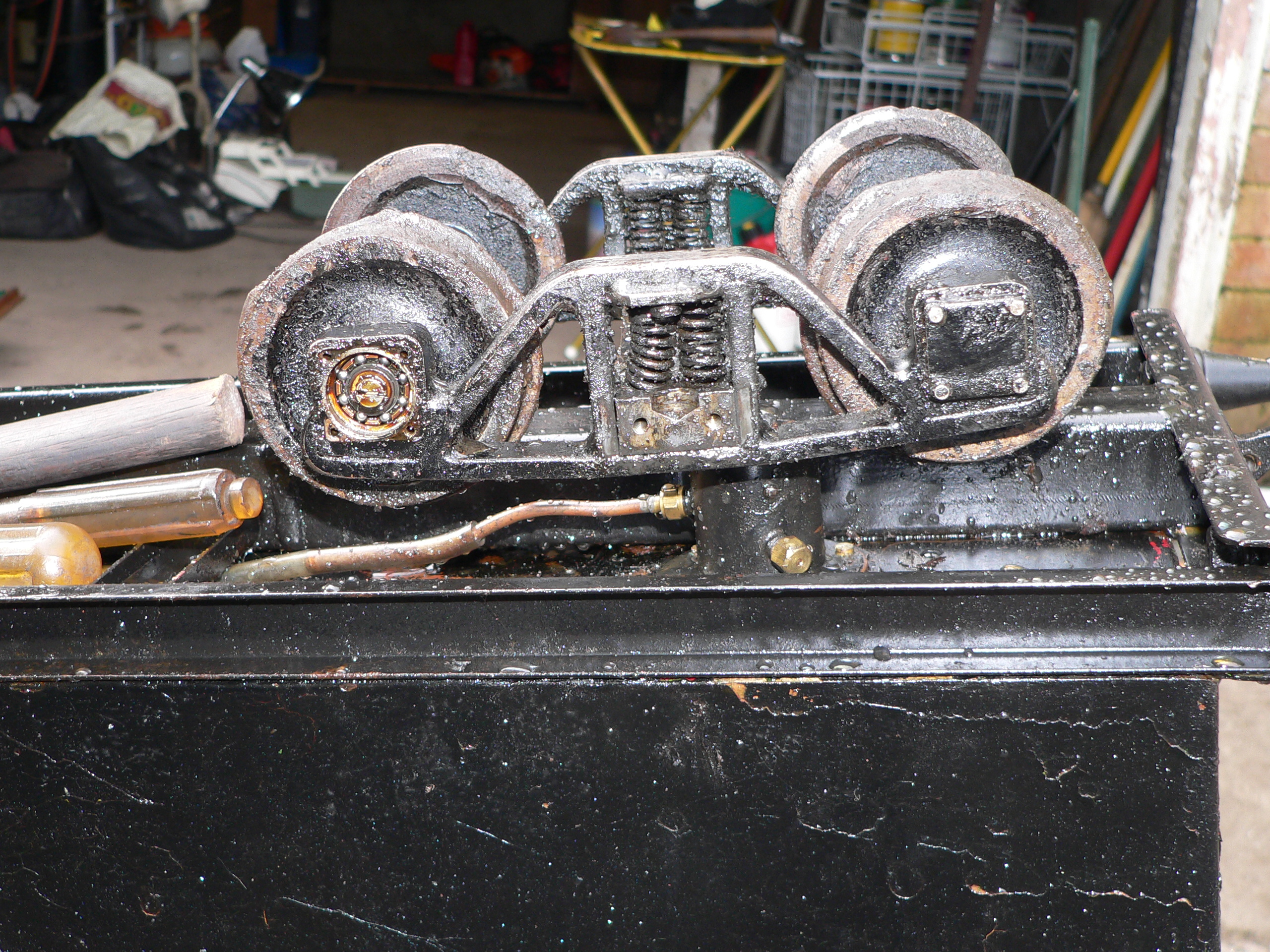
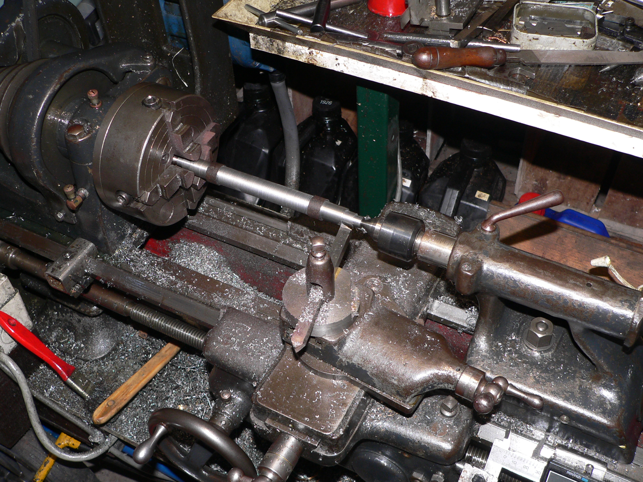
I ordered some wheels from Dinki Di Engineering in Adelaide. They advertise 80mm steel wheels with AALS profile flanges which is just what we needed here. The machining quality is excellent. Ian Thomas (Dinki Di) also offered axles and supplying the wheelsets complete but I decided to make my own axles. The difficult bit was machining the seats for the wheels to 0.6894" so the wheels would be a good press fit but still removable if required. Six of the eight seats turned out well, one was a bit tight, and one was loose and required Loctite to secure the wheel.
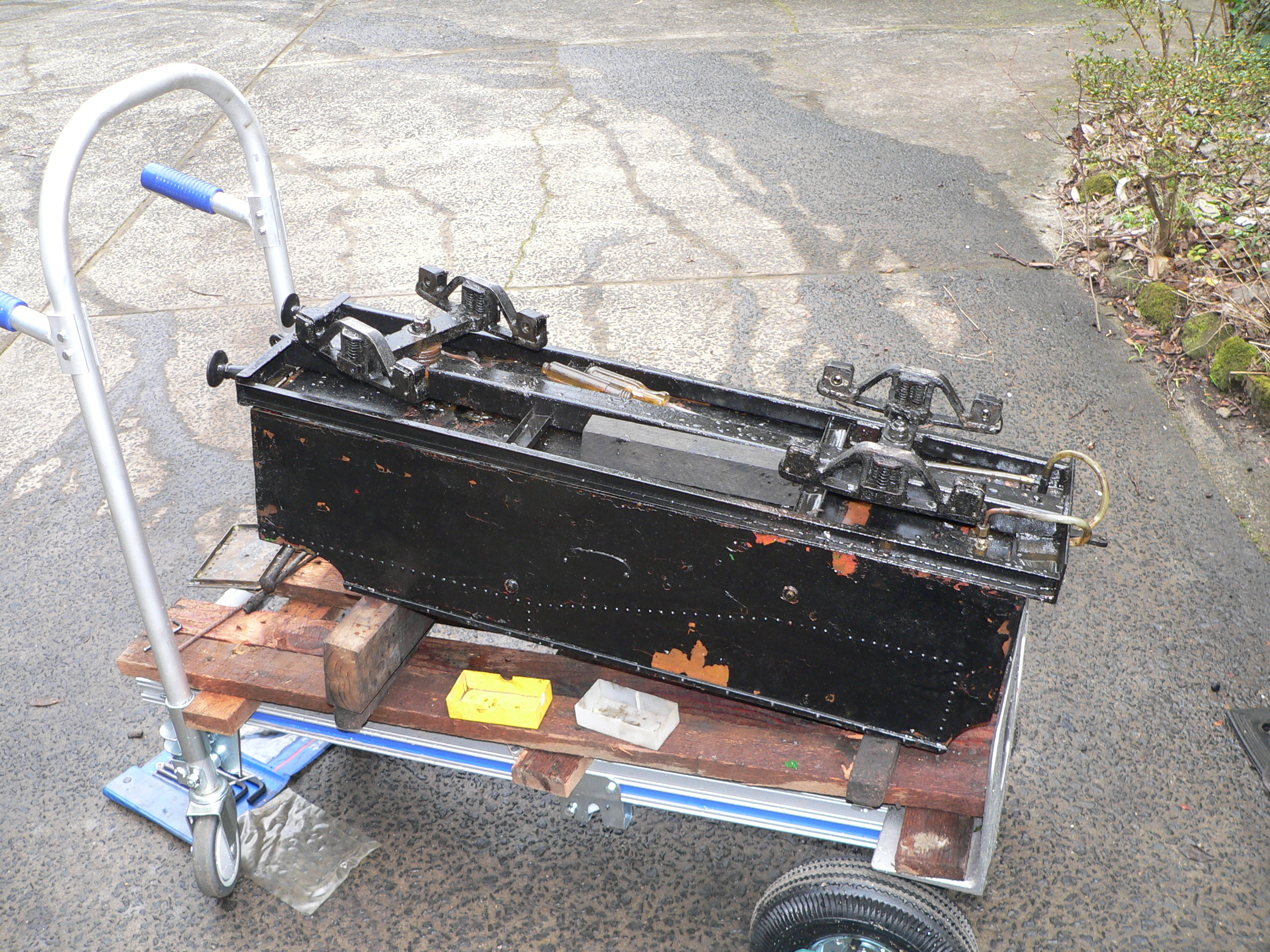
The tender has a hook coupling at the back and it's welded to the frame. Rather than cutting it out I left it and fitted an AALS standard clevis to the underside of the frame. The coupling pocket at the front was too high and the holes for the pin were too large. I enlarged the pocket hole and fitted sleeves to suit a standard 1/4" coupling pin. My brother made new footpegs to replace the 3/8" carriage bolts that were previously used and later made some coupling pins which gave him an excuse to try his new knurling tool.
For the initial test I sprayed the body with KBS Grey paint and sealed some leaks in the tank. The test run at Galston went well and the loco ran for hours until it was full of ash and most tubes were blocked. It steamed better than last time which was amazing because it had a steam leak in the smokebox which we discovered during cleaning the next day. Of course there is a slight scale difference here because the loco is 2.5" scale and the tender is 1.125" scale. Hopefully most people won't be bothered by this and the tender will look better when properly painted.

There was a leak at the steam header in the smokebox and the only way to to remove the header was to undo the bolts some of which were obscured by the petticoat. The chimney was secured by four 6BA bolts fitted from inside the smokebox. These bolts were perpendicular to the smokebox and angled in towards the petticoat. Removing these bolts (especially the back ones) was extremely difficult and refitting them would be even worse.

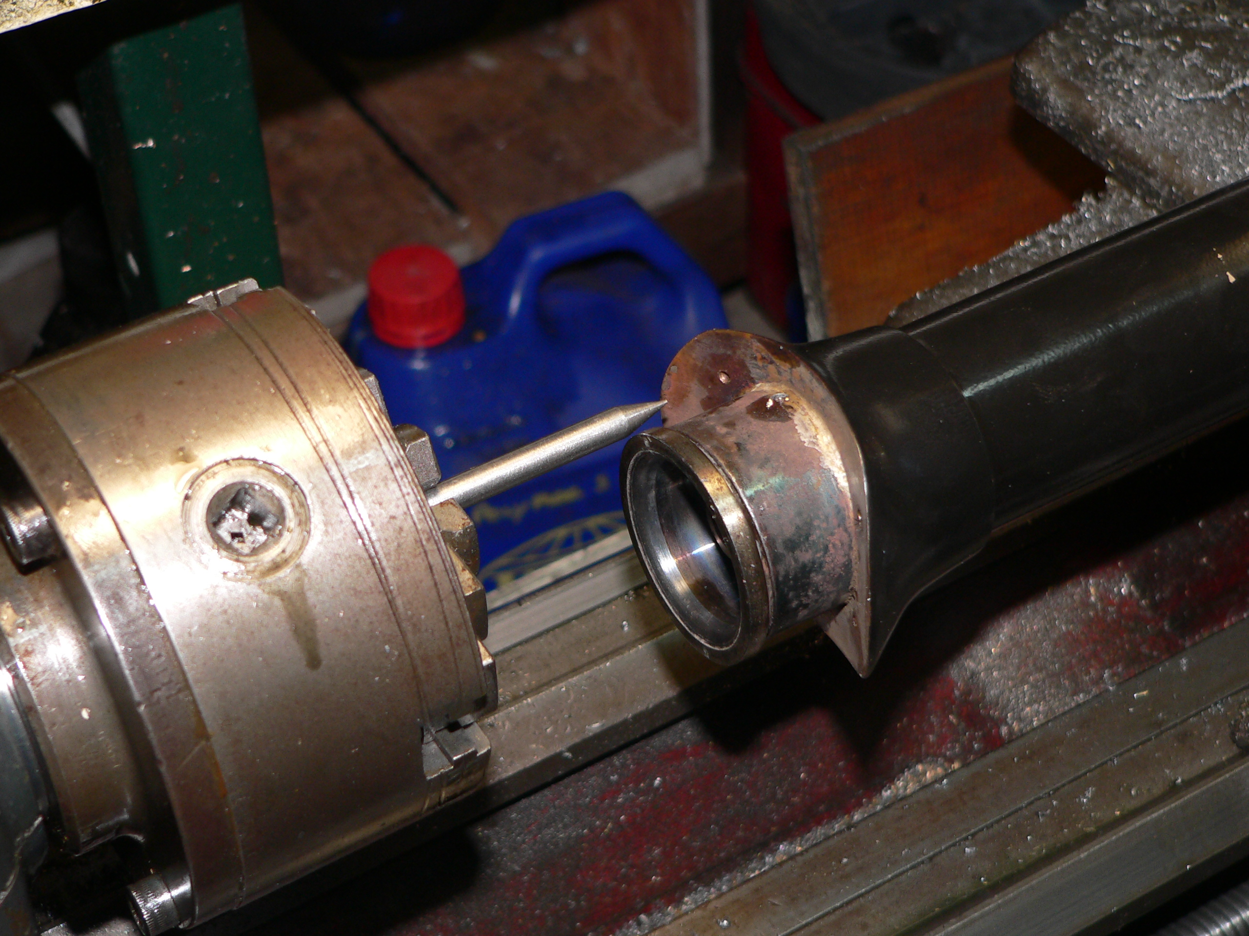
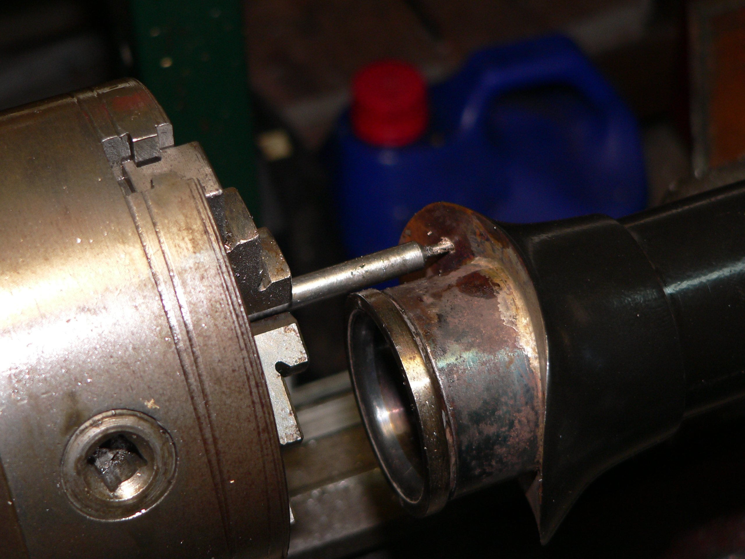
The solution here is to drill vertical holes in the chimney skirt and fit studs that extend down past the bottom of the petticoat. Spacers (not shown) are required above the nuts when fitting the chimney. These spacers have a slanted top to match the smokebox. To drill the vertical holes I machined a piece of rod so it had a point at one end (to align the chimney) and a drill protruding 9mm at the other end. Then I mounted the chimney on a vertical table on the lathe and aligned one of the angled holes using the point then drilled the new hole using the drill end. Finally I tapped the new hole. Repeat three times then fit the studs.

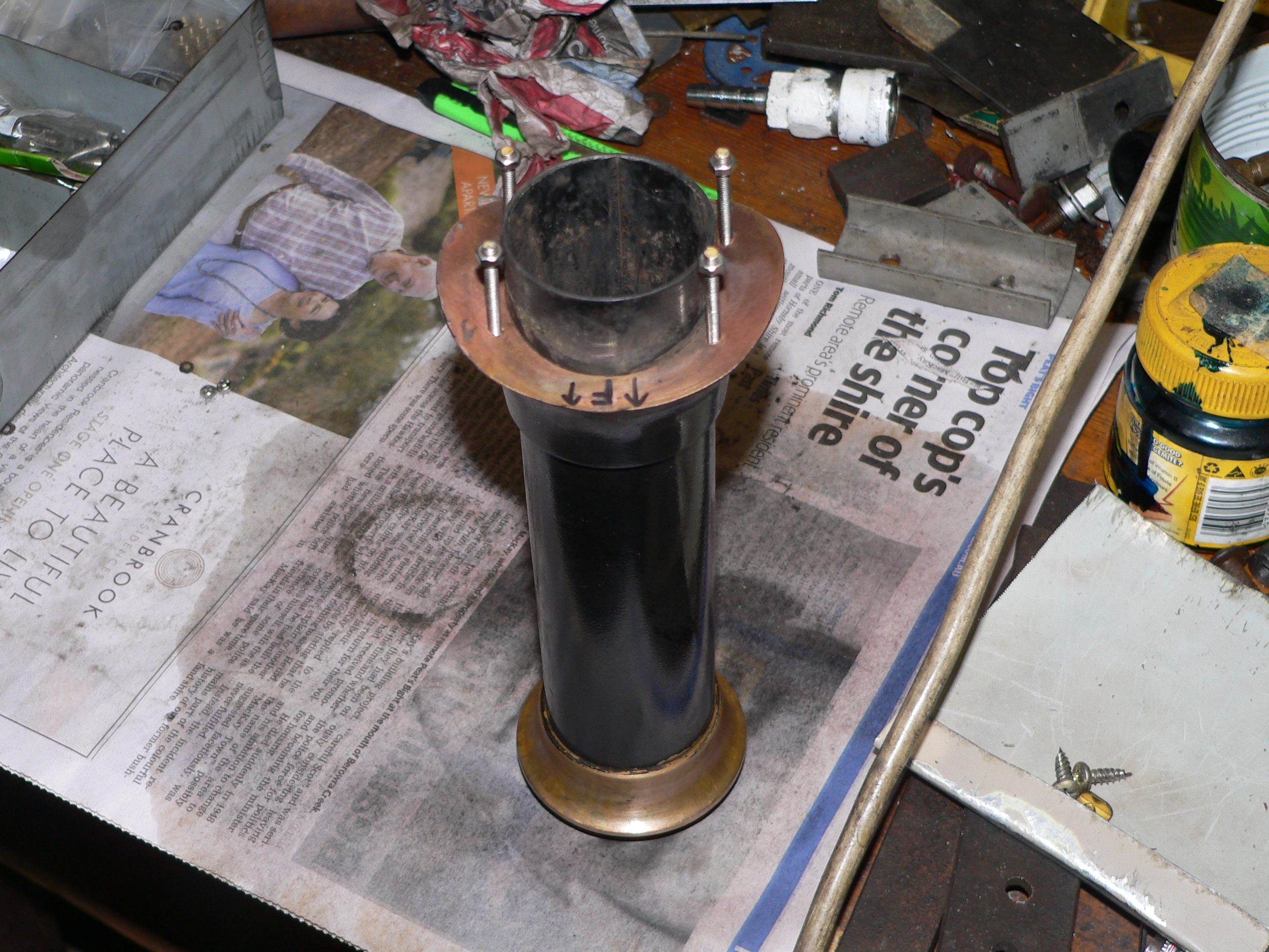
After enlarging and aligning the holes in the smokebox the modified chimney was positioned in place and the spacers and nuts fitted. The spacers are just short pieces of brass tube. Assembly is still a bit fiddly but it will be much easier to remove and refit the chimney if required. Notice the blast pipe extension and sophisticated blower arrangement in the second photo.
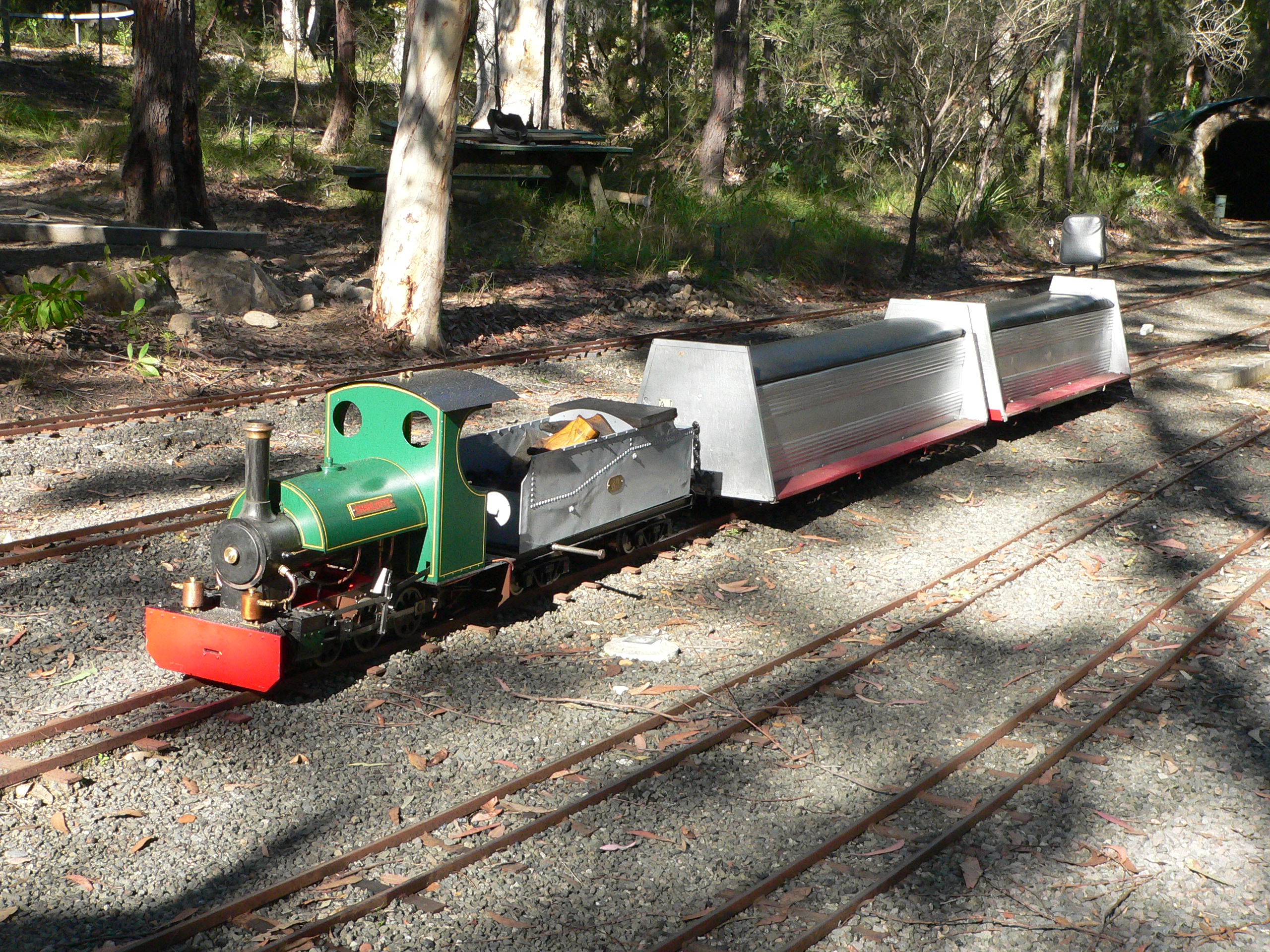
After fixing the steam leaks in the smokebox and doing a test steam I took Charlotte out to Galston for another test. It ran well hauling two carriages with three people for hours until finally all the tubes blocked. The tender holds enough water and coal for such an extended run. The loco does need an ejector to work the vacuum brakes in the carriages. This is high on the to do list. Another suggestion is an angled plate at the front of the grate to reduce the amount of ash that falls forward and blocks the tubes. This run has been the best so far and the loco is looking better all the time.

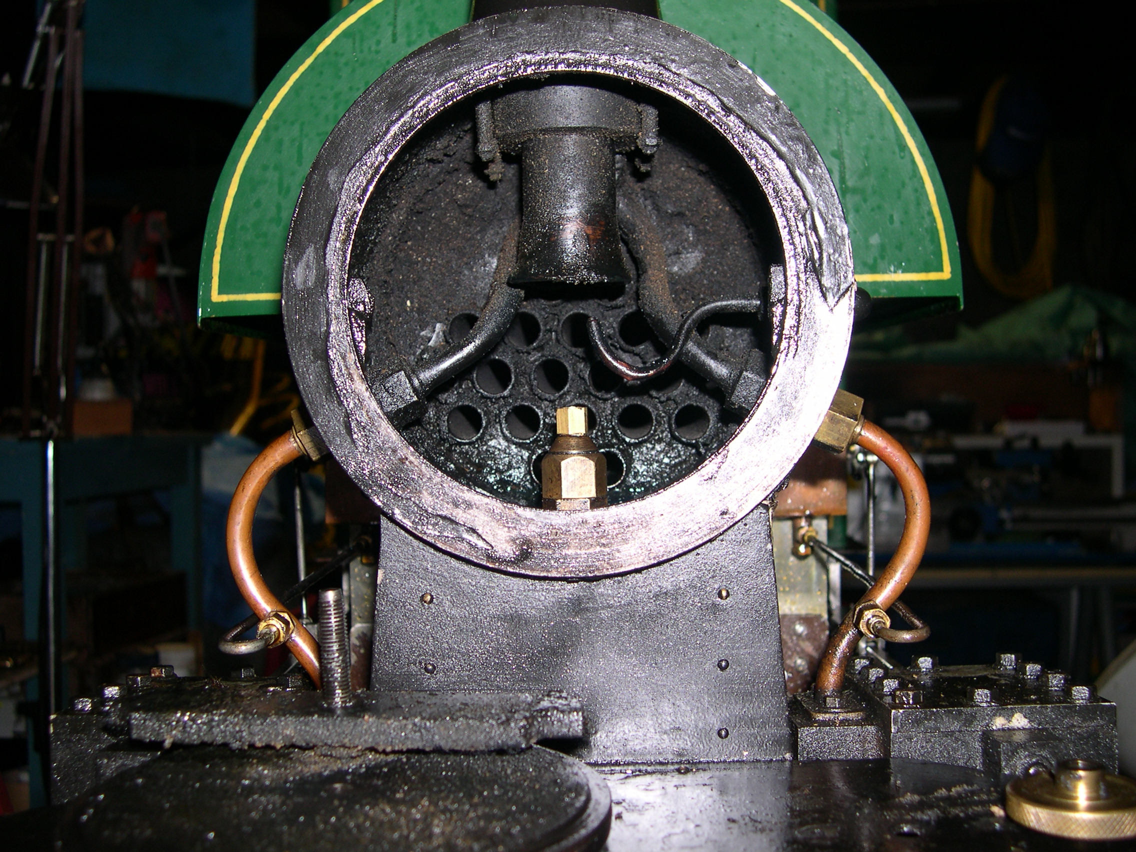
The Bagnall boiler has a circular firebox with a removable grate assembly. The grate is higher than some of the firetubes and there is a vertical plate at the front of the grate to restrain the fire. But ash that gets over this plate blocks the firetubes. The change here is to fit an angle plate to the front plate. The original plate is badly burnt and the new plate should protect the old one and also (hopefully) reduce the amount of ash that gets carried forward and blocks the firetubes.
Testing has shown the efficacy of this angle plate. However, it does get very hot and has a limited lifetime. Periodic replacement is required.
The locomotive has a wind on handbrake and the original riding car has a good manual brake. But since the riding car has been replaced by a tender with no brakes all we have left is the wind on brake on the engine. This is not sufficient when hauling passenger carriages so the solution is to fit an ejector and piping so we can use the carriage brakes. All club carriages must have at least one bogie with vacuum brakes.
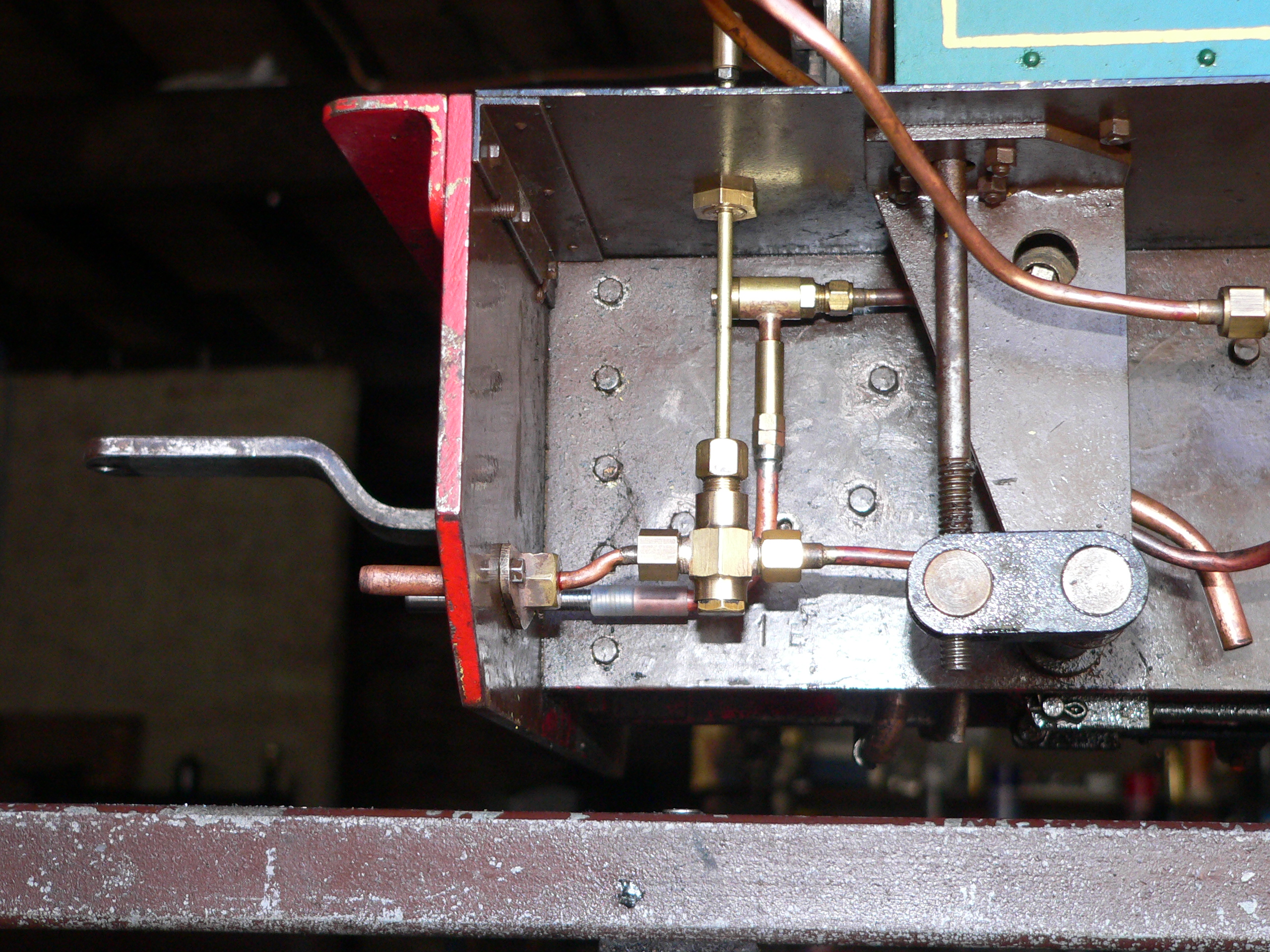
Since I replaced the steam-controlled drain cocks with mechanical cocks we had one valve spare on the turret in the cab. So I used this valve to supply the ejector which has been fitted under the footplate. This ejector has a check valve underneath and a pipe to the connector on the drag beam. The tender has piping from the front to the back buffer beam and also a leak valve which is used to release the vacuum. A proper setup on the engine would also have a vacuum pipe to the front buffer beam and also a connection for a vacuum gauge in the cab. These extras are a future job.
In the picture here the ejector and piping are partially obscured by the injector water valve and its piping. The ejector is just under the footplate and has its check valve underneath. Then we have the bent pipe to the connector on the drag beam.
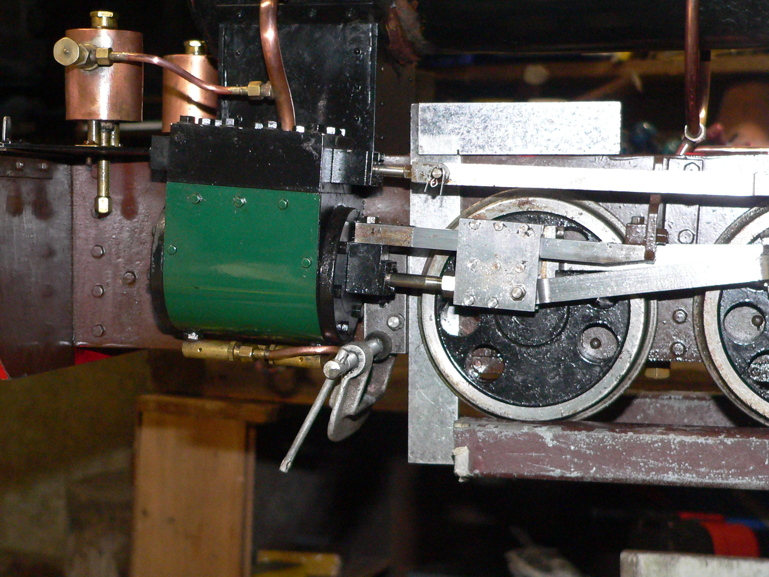
The displacement lubricators mounted in front of the smokebox didn't work probably due to the length of connecting pipes from the lubricators to the steam pipes. So I fitted two mechanical lubricators above the motion brackets with pipes to the original connections on the steam pipes. The reciprocating motion for these lubricators comes from the vertical movement of the valve rods. I chose the vertical movement because it is fairly constant for all positions of the reversing lever whereas the horizontal movement reduces when the lever is moved from full gear.
I had to reposition the stationary pawl on one lubricator because they're not designed to operate with the crank arm horizontal. I also bent the spring ends so it would sit along the crank arm and not clash with the link to the valve rod. The mounting points for the vertical link were designed so the vertical movement in the valve rod would result in 1.5 times the required movement to advance one click on the ratchet wheel. The vertical link can be adjusted so the travel starts 1/4 of a click early and finished 1/4 of a click late so ensure the lubricator reliably advances one click each time.

The whistle used to be mounted on the back buffer beam and the steam pipe wrapped around the outside of the footplate which was less than ideal. Also, why would anybody have a whistle that directs the noise towards the driver ? Luckily the whistle just fits on the cab front above the saddle tank. I made some mounting brackets and fitted the whistle to the front of the cab and remade the steam pipe to suit.
The whistle works better now because any condensation dribbles out rather than staying in the cylinder. And it's a great decoration for the loco.
The water gauges use 5.5mm (7/32") glass tube with white and blue stripes to assist in checking the water level. These glasses weren't positioned correctly (blue line off to one side rather than being at the back) so I decided to loosen the gland nuts and twist the glasses to the optimum position. Of course one glass then leaked and I skillfully managed to break it when trying to fix the leak.
Unfortunately this 5.5mm glass seems to be a thing of the past and unobtainable now. I had a length of 5mm glass and I managed to cut a 50mm length as the replacement glass. However the holes in the gland nuts are too big for this smaller glass so I made replacement nuts and also the sleeve that sets the lower visible water level so it is 10% above the firebox crown. The new glass doesn't have the stripe at the back but it will suffice until I get some 5mm lined glass.
The optimum O-rings to seal here are P5 (metric) or 008 (imperial). I used slices of soft plastic tube supplied by Kelly when I bought the glass tube years ago. The suggested seals now are 5mm x 1mm Viton rings.
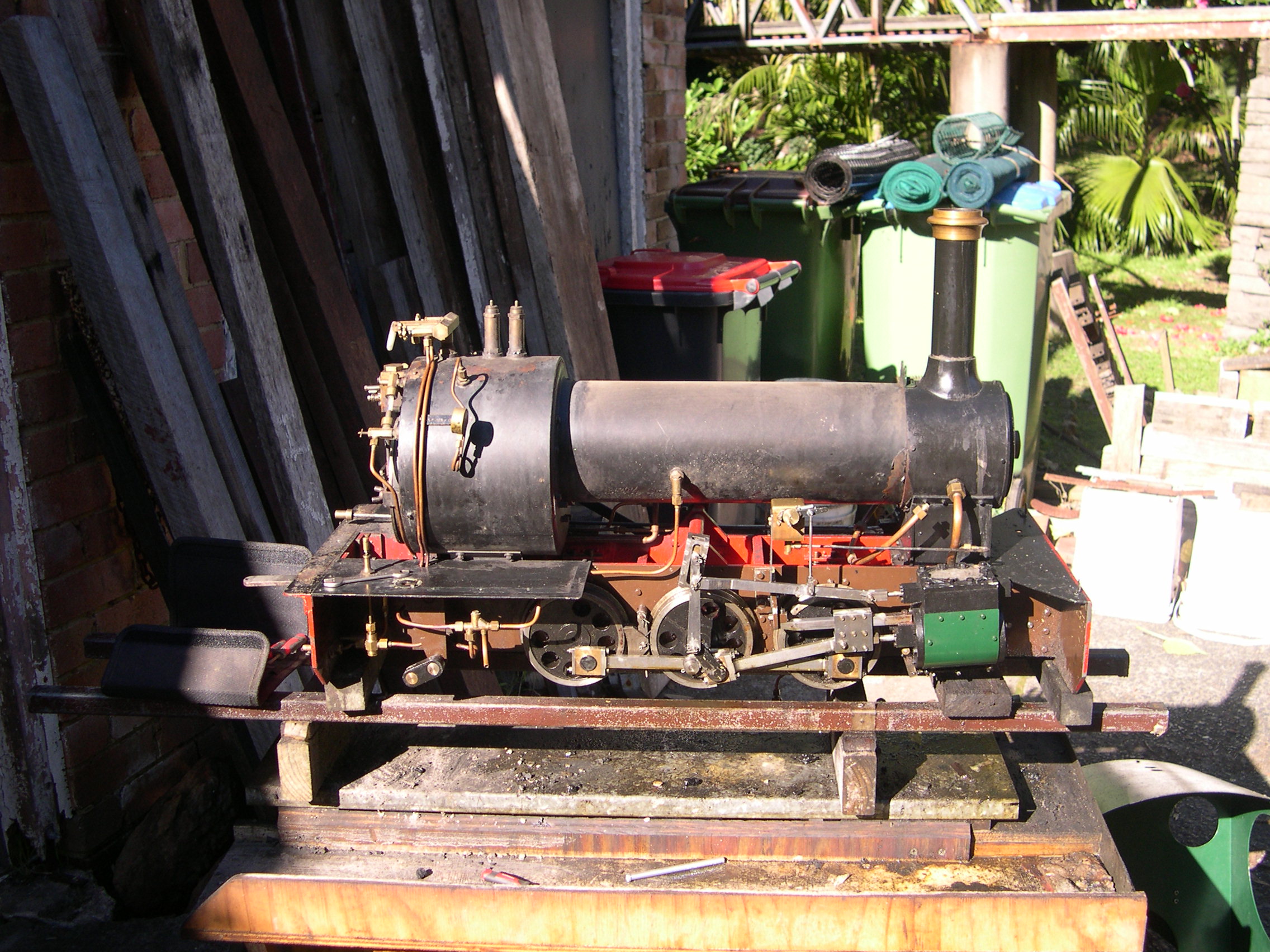
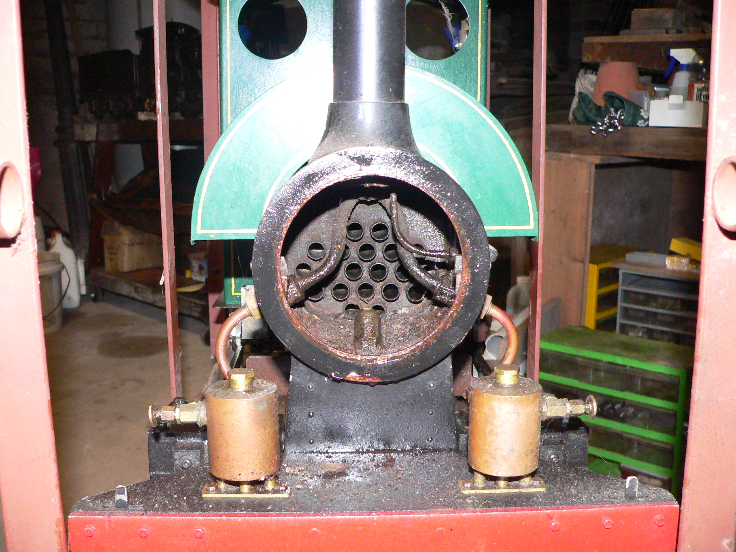
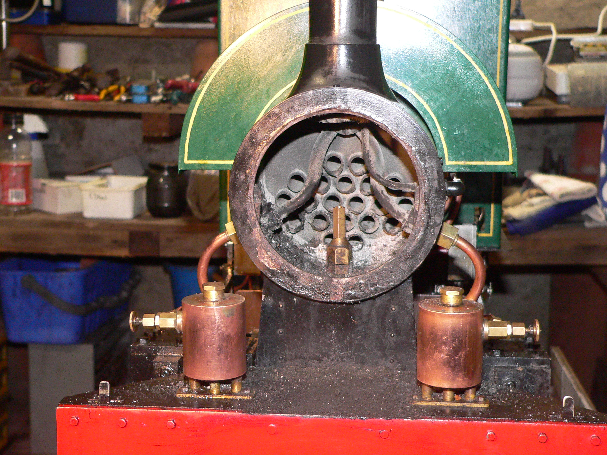
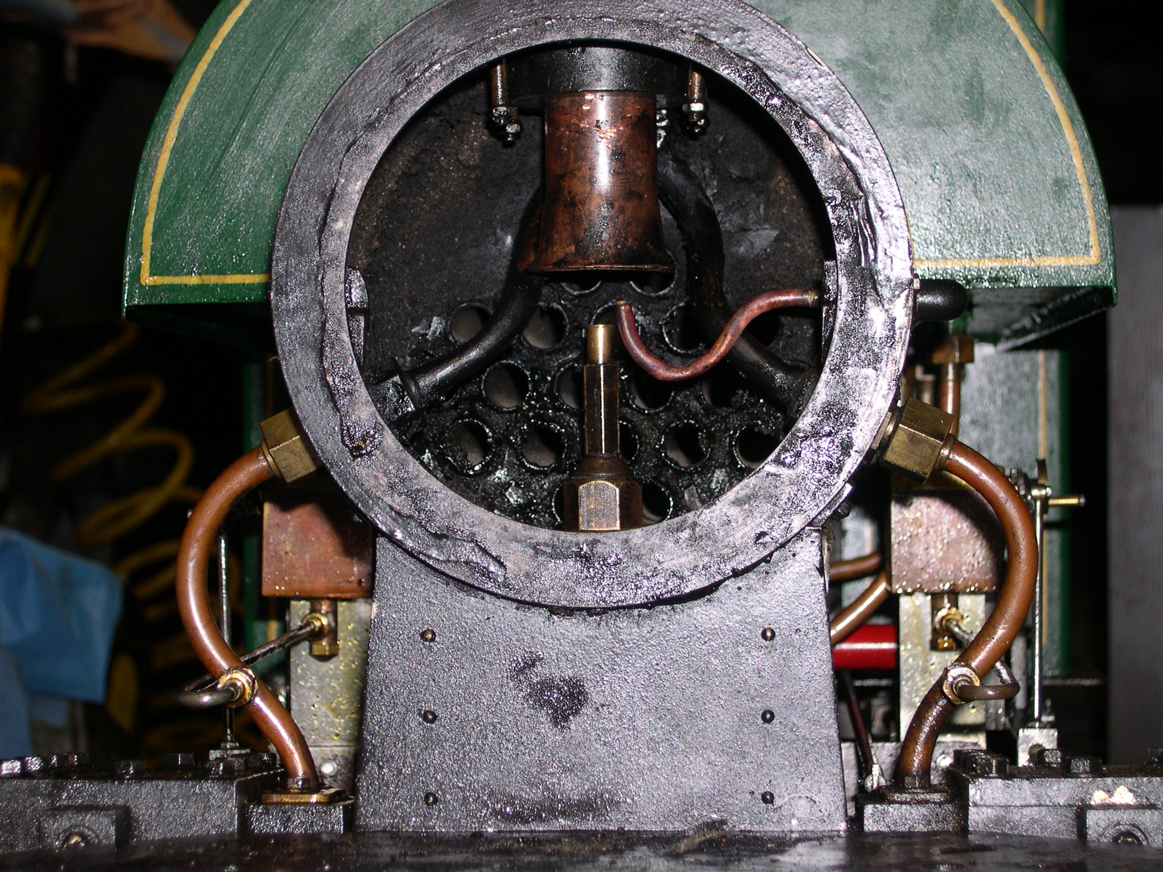
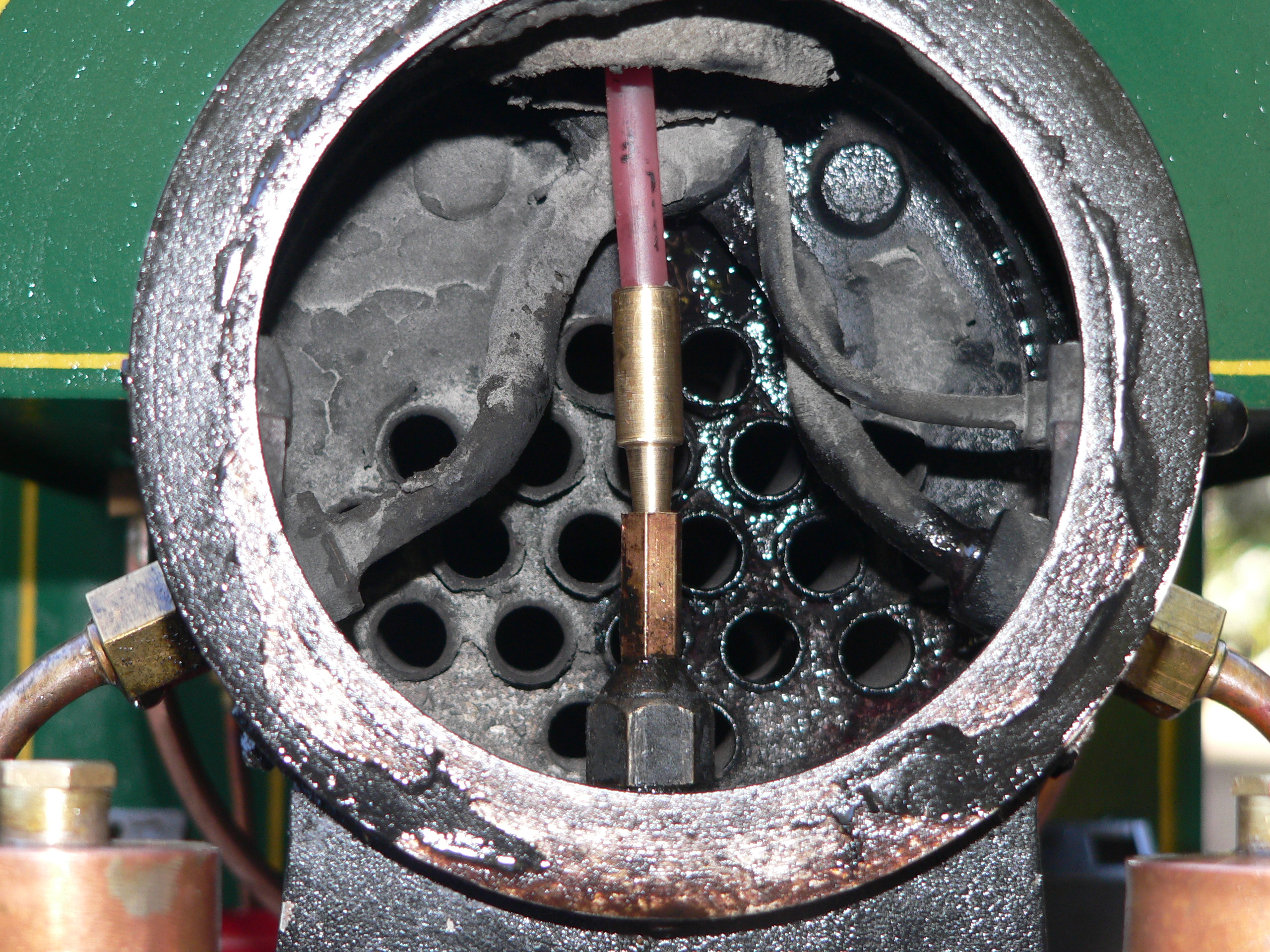
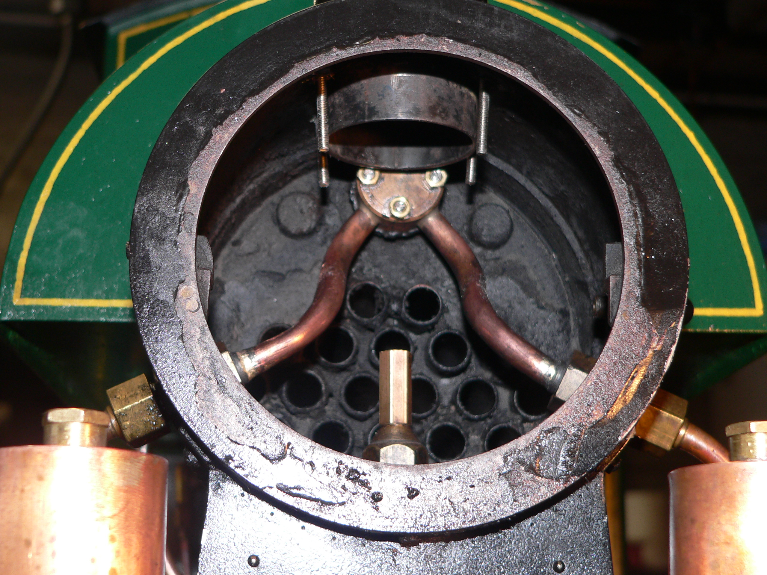
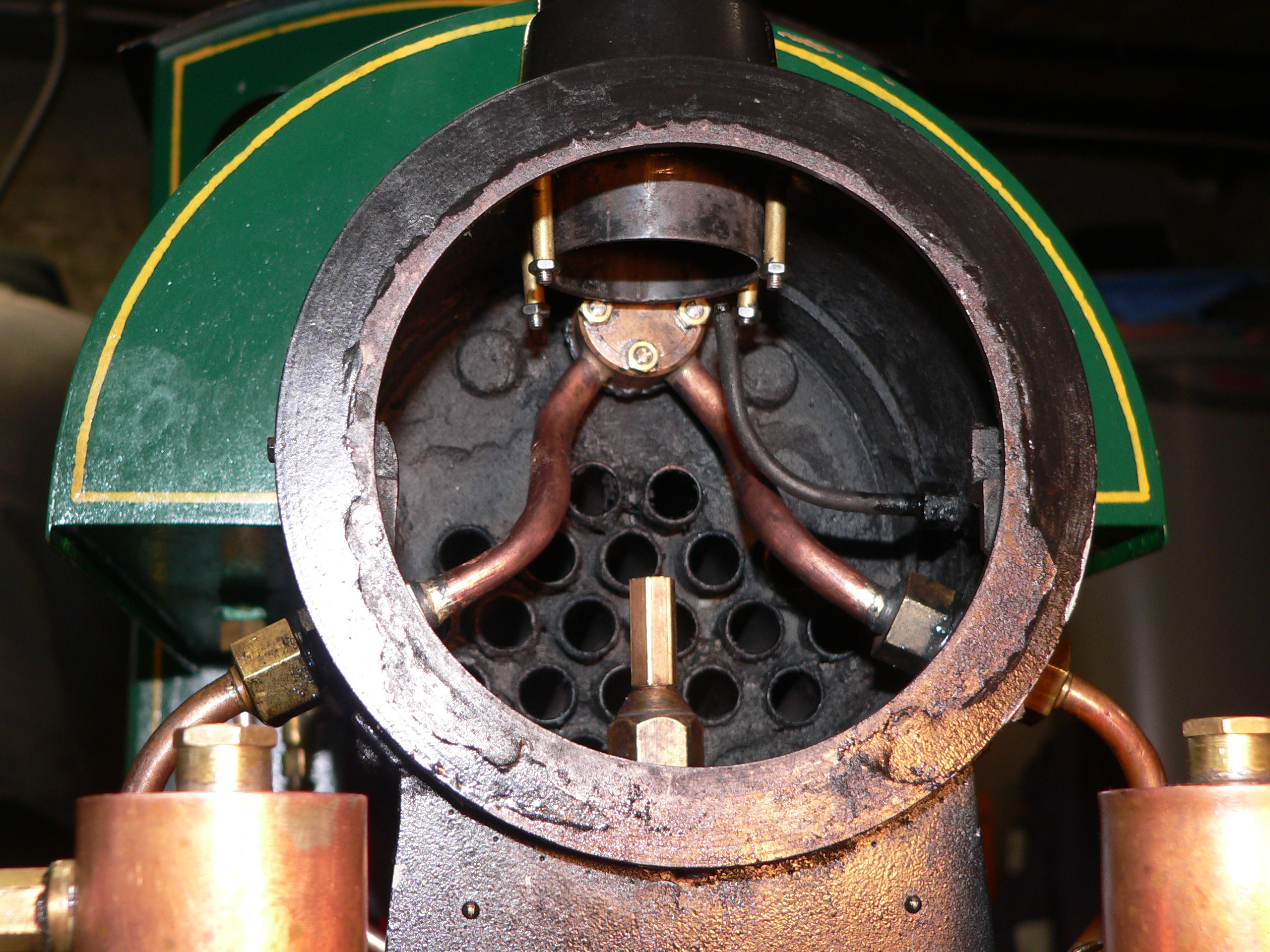
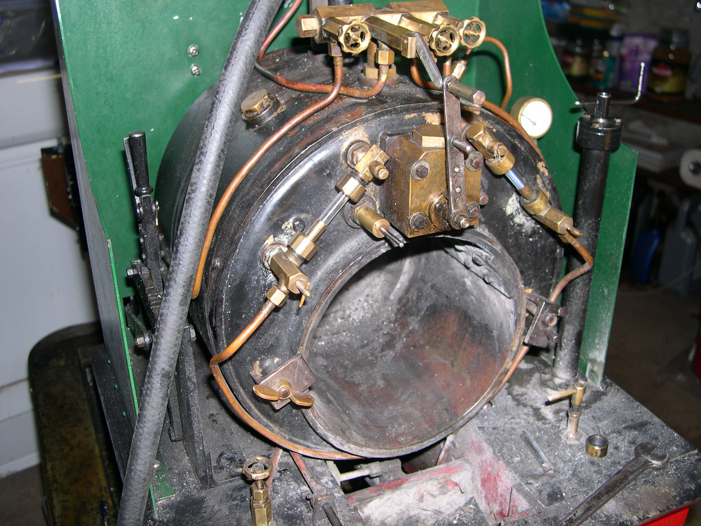
This picture clearly shows the Bagnall boiler. The large barrel at the back contains the circular firebox which extends up towards the top of the main barrel.
The main barrel is full of flue tubes and the top quarter can be steam space. But if the boiler is full the only steam space is the top of the firebox barrel. The inner firefox is circular with the grate about one third from the bottom with the ashpan underneath. There is a vertical plate at the front of the grate to stop the fire from falling forward and into the flue tubes. One issue with this type of boiler is that if ash or coals get over the plate they can't escape and will block the flue tubes.
There is no lagging or cladding on this boiler - an unusual omission. Lagging the main barrel should be doable but covering the firebox area will take much more work.
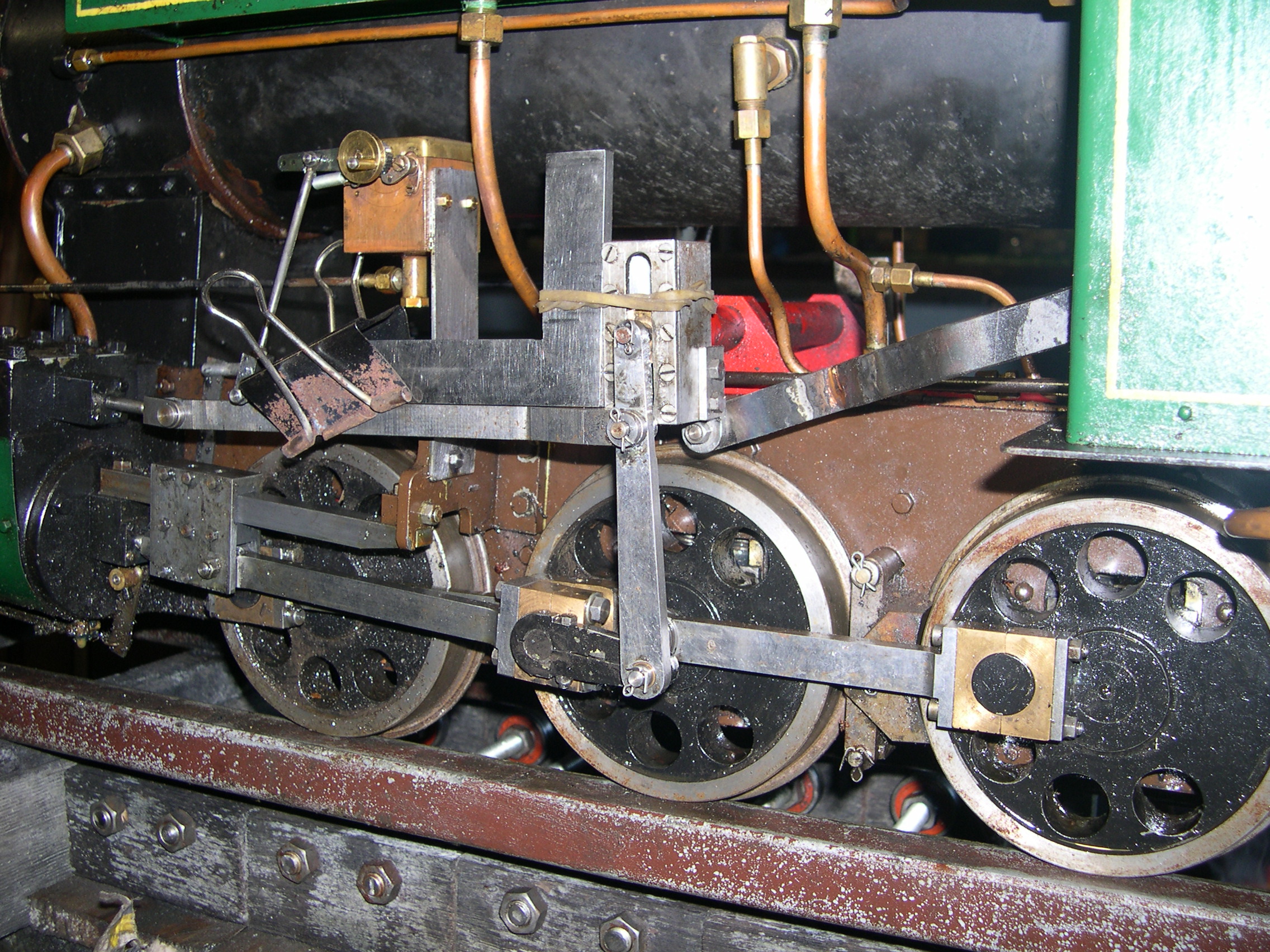
The loco wasn't running very well after some recent fixes where my changes had made things worse. So it was time to consider the valve gear and possible adjustments. There is very little that can be adjusted with the Hackworth gear.
The reversing lever has equal travel from mid-gear to forward and reverse. But the reach rod crank pin on the expansion link was about 30 degrees back and this caused unequal inclination of the expansion link. The inclination for full reverse was much greater than that for full forward. One solution would be to set the reach rod length so the link has some inclination in mid gear. A better solution would be to have the crank pin in the correct location.
Luckily I found I could reverse the crank bracket so the pivot is 14 degrees back. This is very close to the reach rod inclination which is 15 degrees. So I reversed the bracket and modified the reach rod. The transverse offset from the bracket to the reversing lever is now 43mm which is not good. It was 19mm before. But the reach rod is strong enough to handle the forces with this offset.
To determine the reach rod length I set the expansion link perpendicular to the valve rod when the die block is at the expansion link pivot point. Then with the reversing lever in mid gear I could clamp the two parts of the reach rod together and braze them. The expansion link inclination is now 34 degrees in both forward and reverse. /p>
Last modified 2023-04-25