
Miniarc 142 Welder
|
Miniarc 142 Welder |
|
Recently (2008-05-29) I purchased a Miniarc 142 inverter welder from TokenTools. Similar welders are available from other sellers in Australia. This model uses IGBTs instead of MOSFETs for supply switching. This is meant to be better but I don't know enough about transistor technology to comment here.
This report shows what's inside the unit and details good and bad points I've noted. I was thinking of buying at least one other model for comparison but this unit seems fine so I'll save my money. If you're considering such a welder then the comments here might help you make a more informed decision when assessing the available models. Although this model is basic it does have some design features that are better than the competition.
What did impress me was that I could test a demo unit at the shop provided I brought my own gear (scrap, rods, helmet, hammer, etc) and that I could get answers to all my questions. The service was so good that I bought the welder on the spot.
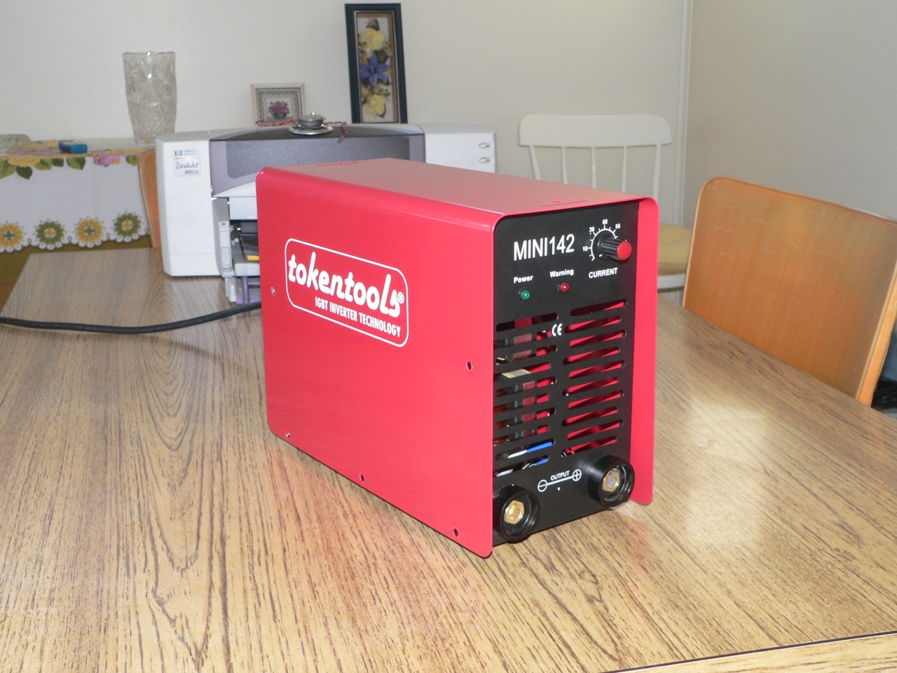
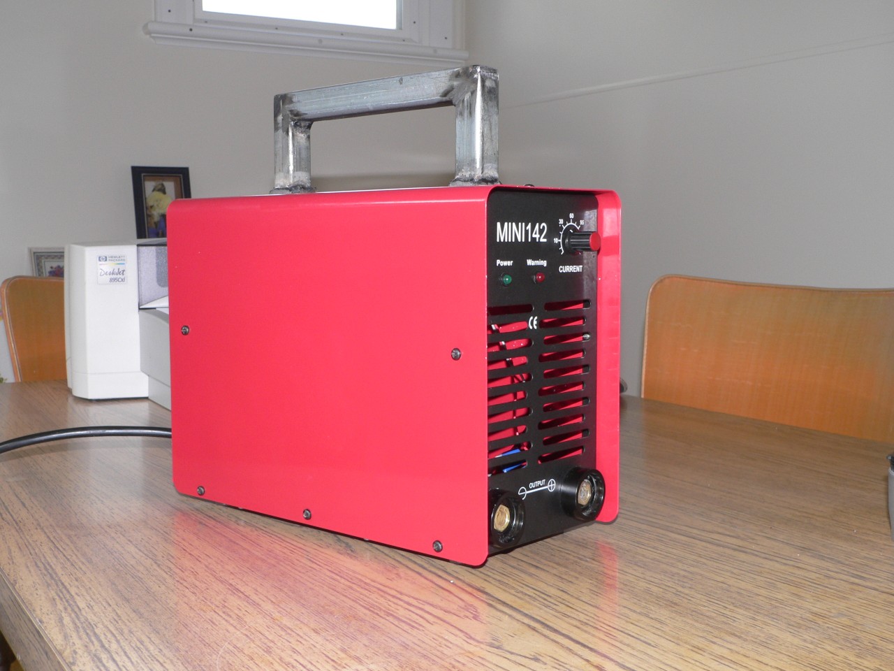
Here is the welder in almost original condition. It came with a shoulder strap but since I don't regard a welder as a fashion accessory the strap was discarded and will be replaced by a handle. The dial on the front panel is the current control. The current range is from 10 to 125 amps. Most of the front panel is the exhaust port for the cooling air.
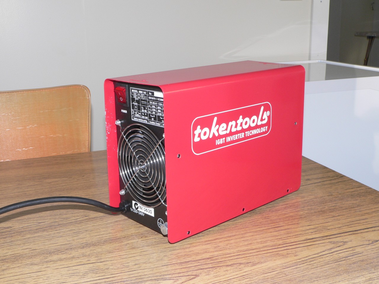
The back panel contains the power switch and fan. Putting the power switch at the back seems a bit silly but it does keep the mains wiring at the back of the unit and away from the internal heatsinks to avoid the chance of damaging the insulation. Another possible reason here is that the fan should be allowed to run for a bit after welding to dissipate the heat generated by the electronics. Making the switch less accessible might encourage this. Do you believe me ? It might be true. Bearing this in mind I would like a control switch on the front panel to deactivate the inverter. Then I could leave the unit (i.e fan) running and avoid the risk of shorting the electrode or getting a tingle while changing rods.
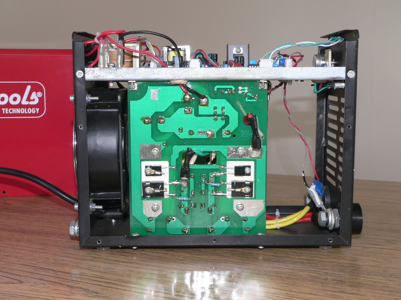
This view of the left-hand side shows the power board. The IGBTs on the power board switch the rectified supply and are controlled by the little transformer at the back of the control board. The two IGBTs and the smaller diodes are visible on the power board. The diodes catch the voltage spikes that occur during switching. The board is sealed to protect against dirt and moisrure.
The platform near the top supports the control board. The large fan on the back panel and the slots on the front panel provide good airflow for cooling.

This top view shows the control board. At the back are the power switch and bridge rectifier. The platform provides a barrier to stop dust and dirt from below so the control board should stay clean and functional. The board underside is sealed but the top is not so it will be sensitive to moisture and dust. The control circuitry uses feedback from the OCV monitor, the transformer input current detector and the current control potentiometer. The circuit generates 25kHz signals to drive the IGBTs via the isolating transformer and uses pulse width modulation to regulate the welding current and limit the open circuit voltage.
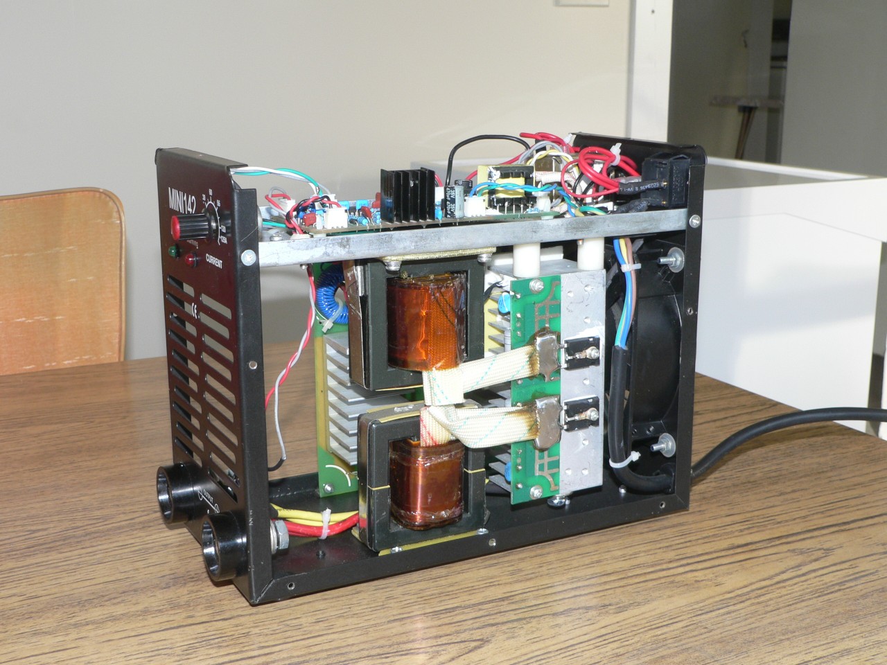
This right-hand side view shows the transformer, choke, and output rectifiers. The output from the transformer is half-wave rectified and the choke and output capacitors smooth this output to produce a better DC supply for the electrode. There is a thermistor on the heatsink behind the rectifiers. This thermistor is monitored by the control board so the welder will shutdown if the rectifiers overheat.
The welder now has a somewhat oversized handle. The handle is large so I can move the welder while wearing gloves. The logos on the case were scratched so I removed the white paint using my fingernail and then some "Bug and Tar Remover" to lift the stubborn spots. I'm not against branding but the damaged logo did look untidy so it had to go.
It is a nice little portable box and it's amazing that such a tiny animal can output so much grunt. However, it does need a 15A supply which isn't very common in my area. No doubt some users will be filing the earth pin on the plug and overloading a 10 amp GPO (not recommended). The peak input current (Imax) is listed as 25 amps and the average input current (Ieff) can be up to 13 amps.
DC welding is a new experience for me. The arc is smoother and more continuous than that from a transformer welder. The OCV is higher (approx 70V) and this means it is easier to start the arc.
The Miniarc is a constant current device so its personality is different from my transformer welder (Abel 130). I tested using both my welders alternately and have to say that the Miniarc is much easier to use. When using Gemini E4112 rods I can set the current to much less than the transformer welder (say 35 amps versus 60 amps) and have a nice little puddle without overheating the surrounding area of the job. I couldn't achieve this difference when using Murex E4112 rods (not sure why).
With 16g plate I managed to weld using a 1.6mm rod at about 20 amps. On the transformer welder I need about 40 amps to keep the arc alive and even then it is very fragile. Presumably the constant current characteristic of the inverter welder is helping here. It certainly is much easier for me to weld thin plate.
In fact this unit is better than a constant current device. At very low voltages (e.g. rod about to stick) the current increases and can exceed 130 amps. This makes it easier to strike an arc and harder to stick a rod. At high voltages (long arc) the voltage detector kicks in and the arc begins to splutter.
I'd really like to improve the current control knob. It is tiny and even a small movement has a significant effect on the weld. A larger knob would definitely help and perhaps a range switch so I could select 10 - 70 amps or 50 - 125 amps.
The airflow design of this unit is good. Some models have a smaller fan and less exhaust ports so they might be more prone to overheating. This box sucks air in the back and blows it out the front which seems much better than models that suck in the front and/or have side vents.
The unit sits on four metal pads (the base of the chassis). I've fitted plastic feet so it is less likely to slide and won't scratch a delicate surface. These feet soften the impact when I put the welder down and they also raise the unit slightly which makes it easier to connect the cables.
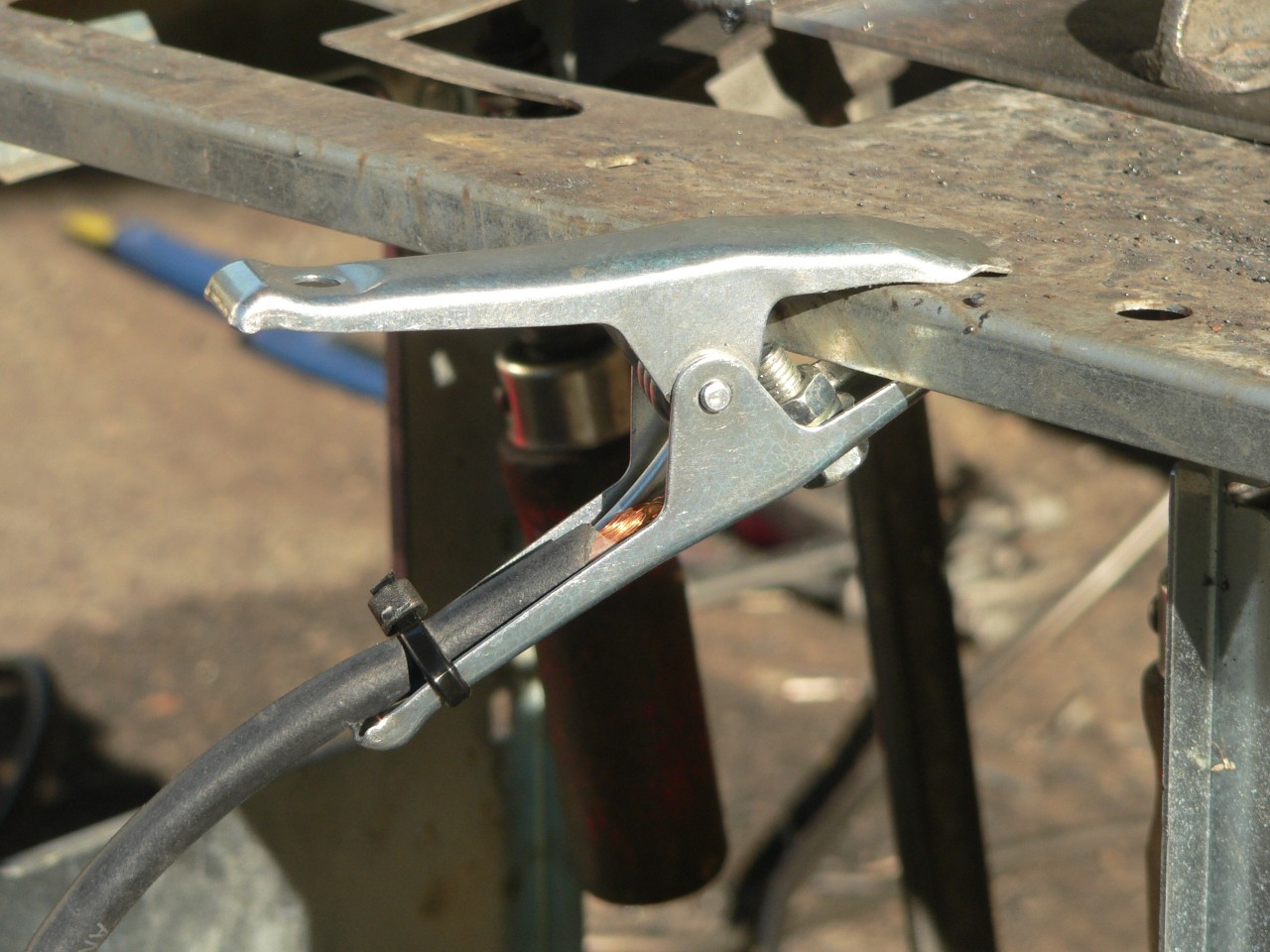
The earth clamp is a feeble affair and the cable attaches to the end of one of the handles. The fixing bolt is right where I squeeze the handles (ouch) and the cable will quickly break due to flexing as there is no secondary restraint. To improve things I drilled a hole near the pivot, fixed the cable there, and used a cable tie to secure the cable at the end of the handle. There is no braid connecting the arms of this clamp. The best part of this clamp is the spring so now I've fitted a Weldmart 200A clamp which is a much nicer piece of work.
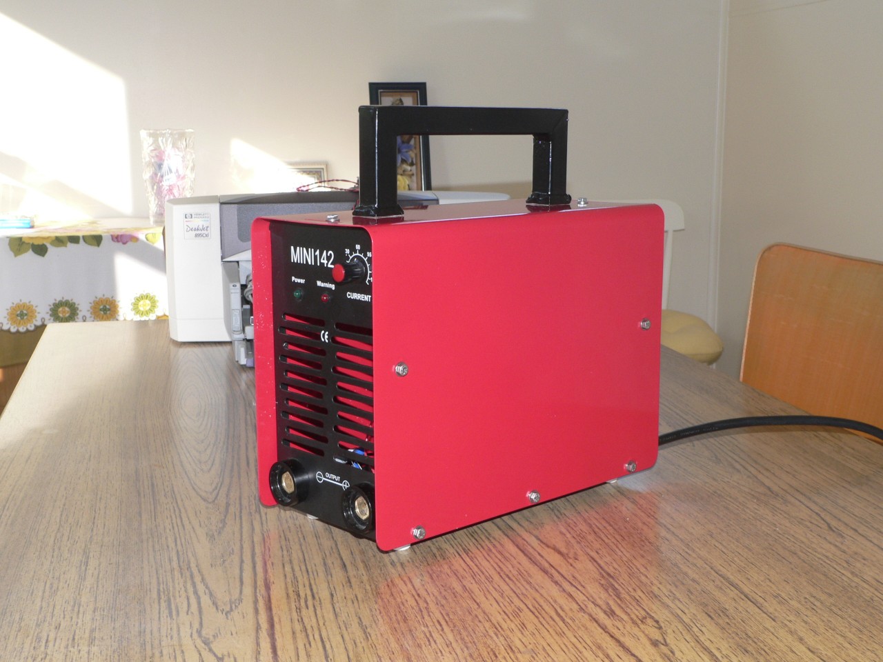
The unit comes with a shoulder strap which tends to get in the way if you're not carrying the unit around. I removed this and fitted a homemade handle (training project for my new welder) which is much more convenient for me. Here I've painted the handle and polished the unit so this is the best it will ever look. The next phase is when the welder will get dented and scratched out in the real world.
I replaced the self-tapping screws with S/S bolts and repositioned the fan slightly so it doesn't foul the rear bolts. The idea of a power switch on the front panel has been dropped as I use an inline power switch on my supply line instead. Repositioning the mains cable inside the unit is difficult due to the lack of space. The idea of a deactivate switch on the front panel is risky as I will probably void my warranty.
I've fitted a larger knob to the current control pot. This was more work than expected because the shaft is 4mm dia and most knobs expect a 1/4" shaft so I made an adaptor sleeve (4mm ID, 1/4" OD, with splits down each side). If you want to remove the standard knob the trick is to pull the red cap off and then loosen the phillips head screw underneath. This releases the collet and the knob slides off. This is a good arrangement and the knob won't come loose in service. I'm impressed.
This is a small and lightweight welder and might be serious competition to products from well-known manufacturers. It costs less than most but it does work and comes with a three year warranty so it is an excellent toy for novice welders like me who want to experiment with this newfangled technology.
The case build quality is okay except that the screw holes in the case cover didn't line up with the body so I had to file the holes so the screws would sit flat. I was critical of the build quality but now I've seen pictures of similar welders where the cover looks to be made from much thinner metal which will probably dent easily and offer little protection to the electronics that are close to the cover.
If I had the choice I would still buy this welder rather than the two others I considered. It has the smallest rating (125A) of the trio and yet was the most expensive ($465). I suspected that most units in this price range are more similar than the vendors care to admit but now I'm thinking that mine might be a little better. My model does have a long warranty and the dealer does have a real shop and it is within driving distance. Factors like this make it a much better choice for me. Some models apparently have a CPU and feedback for better arc control and this does sound good. Some models only have a three month warranty and this sounds bad.
Being a inquisitive and troublesome fellow I sketched out a schematic for the welder and decided to change its current detection circuit. The standard approach is to have a coil around one of the leads feeding the HF transformer. I bought a 100 amp 0.01 ohm resistor from Jaycar and connected this in series with the output. I tried a number of ways of controlling the oscillator IC that drives the IGBTs but none were successful. So I've gone back to the original approach. My problem with this approach is that I blew one of the output diodes when I turned the welder on with the leads shorted. Now I've replaced the output diodes with some higher rated devices.
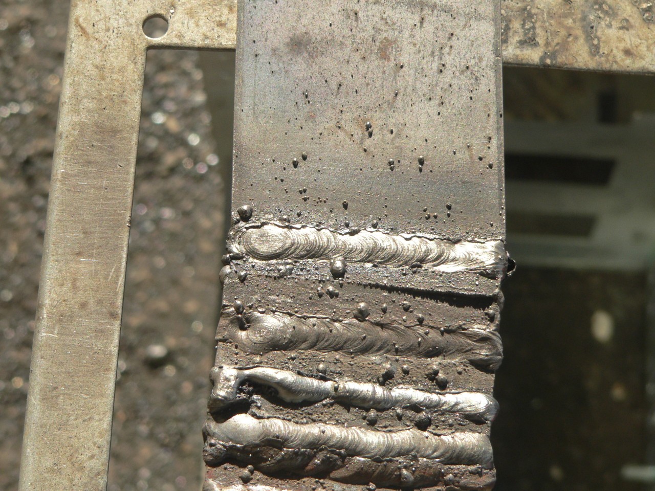
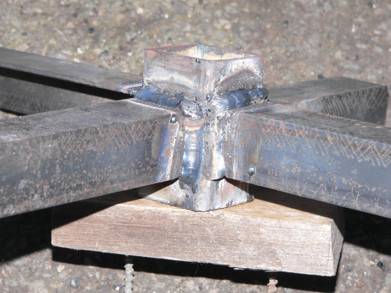
Shown here are a butt weld (topmost weld) on 50x3 plate and some vertical up welds on 3mm thick stock.
Today (2008-06-02) I tried the welder on a real job and it was great. The arc was cleaner and easier to strike. The optimum current setting was slightly less than my transformer welder. The inverter shone in a few places where I had to build up an external vertical corner because I could turn the amps down to lay a bead and still have a stable arc. The power supply was fluctuating due to other tools in use but this didn't affect the welder.
Today (2008-07-07) the welder is still working well. I've changed from DCEN to DCEP and this helps with most welds. Recently I tried laying long beads on maximum amps and the welder didn't overheat or cut out.
Today (2010-03-20) the welder has done plenty of work and it's still as good as new except for a few scratches. The only maintenance so far has been cleaning the dust off the fan and fins inside the unit every few months.
Today (2011-07-31) the welder is still fine. Lately I've seen some little inverter welders that can supply 170 amps and I'm told they're cheaper than mine. The case is plastic and the duty cycle might be a problem but they sure do seem impressive. The extra current might be useful for 3.2mm sticks.
Check my homepage for contact details if you have any questions or feedback. Comments about the content or design of my pages might help me improve this report and will be appreciated. The text size in these pages is variable and specified by your browser settings so you can change it for your viewing convenience.
Last modified 2011-07-31